Reverse engineering plays a critical role in modern mechanical, industrial, and manufacturing engineering, particularly in cases where original CAD data is unavailable, legacy components must be reproduced, or design optimization is required. With the advancement of high-resolution 3D scanning technologies, reverse engineering has evolved into a precise, data-driven workflow capable of supporting design validation, simulation, and advanced manufacturing.
This technical article provides an in-depth engineering perspective on 3D scanning for reverse engineering, focusing on scanner technologies, data processing workflows, accuracy considerations, and a detailed comparison of LiDAR vs 3D scanning. The content is structured to address high-intent technical search queries such as 3D scanner for reverse engineering and what is reverse engineering in 3D, while maintaining a professional, engineering-grade level of detail.
What Is Reverse Engineering in 3D?
3D reverse engineering is the systematic process of reconstructing a digital, editable CAD model from a physical object through geometric data acquisition and computational modeling.
From an engineering standpoint, reverse engineering involves:
- Capturing surface geometry using non-contact measurement systems
- Generating high-density point clouds
- Creating polygonal meshes
- Rebuilding parametric and feature-based CAD geometry
- Validating dimensional accuracy against scan data
Unlike simple 3D digitization, reverse engineering focuses on design intent recovery, allowing engineers to extract functional dimensions, tolerances, and manufacturing constraints from scanned data.
Role of 3D Scanning in Reverse Engineering
3D scanning serves as the primary data acquisition method in modern reverse engineering workflows. Traditional manual measurement techniques (calipers, CMMs) are often insufficient for capturing:
- Freeform surfaces
- Complex organic geometries
- Internal or inaccessible features
Engineering Advantages of 3D Scanning
- Sub-millimeter accuracy
- High spatial data density
- Reduced measurement uncertainty
- Faster acquisition compared to tactile metrology
- Compatibility with CAD, CAE, and CAM systems
These advantages make 3D scanners for reverse engineering indispensable in high-precision engineering environments.
3D Scanner Technologies Used for Reverse Engineering
Selecting an appropriate 3D scanner requires a clear understanding of measurement principles, accuracy limits, and application constraints.
Laser Triangulation Scanners
Laser triangulation scanners project a laser line or point onto the surface and calculate depth using triangulation geometry.
Engineering characteristics:
- Accuracy: up to ±0.02 mm
- Resolution: high
- Sensitivity to surface reflectivity
Typical applications:
- Mechanical components
- Mold and die reverse engineering
- Dimensional inspection
Structured Light 3D Scanners
Structured light scanners project coded light patterns onto the object and reconstruct geometry using stereo vision.
Engineering characteristics:
- High surface resolution
- Rapid data capture
- Excellent for complex surface topology
Limitations:
- Reduced performance in bright ambient light
- Surface preparation required for reflective materials
Handheld 3D Scanners
Handheld scanners combine laser or structured light systems with inertial tracking.
Engineering advantages:
- Flexibility for large or fixed components
- On-site scanning capability
Accuracy range:
- ±0.03–0.1 mm depending on system and calibration
Industrial Metrology-Grade Scanners
Used in aerospace, automotive, and high-tolerance manufacturing.
Features:
- Certified accuracy
- Integration with GD&T analysis
- Full traceability
Accuracy, Resolution, and Metrology Considerations
In reverse engineering, accuracy refers to the closeness of measured geometry to true values, while resolution defines the smallest detectable feature.
Key influencing factors include:
- Scanner calibration
- Surface material properties
- Environmental conditions
- Scanning distance and angle
- Data processing algorithms
Engineering-grade reverse engineering typically requires:
- Accuracy ≤ ±0.05 mm
- High point density in functional regions
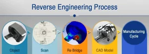
Reverse Engineering Workflow: From Scan to CAD
Step 1: Point Cloud Acquisition
Multiple scans are captured to cover the entire geometry. Registration algorithms align individual scans into a unified coordinate system.
Step 2: Point Cloud Optimization
Includes:
- Noise filtering
- Outlier removal
- Data decimation (where appropriate)
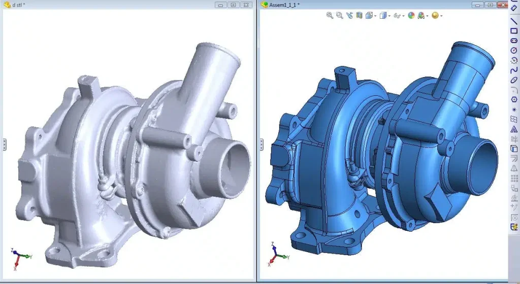
Step 3: Mesh Generation
Point clouds are converted into polygonal meshes (STL/OBJ). Mesh quality directly affects surface reconstruction accuracy.
Step 4: Surface and Feature Reconstruction
Engineers rebuild:
- Analytical surfaces (planes, cylinders, cones)
- Freeform NURBS surfaces
- Parametric features
Step 5: CAD Validation
Deviation analysis is performed between the CAD model and original scan to ensure dimensional compliance.
LiDAR vs 3D Scanning: Engineering Comparison
One of the most common technical questions is LiDAR vs 3D scanning for reverse engineering applications.
LiDAR Technology Overview
LiDAR (Light Detection and Ranging) measures distances using time-of-flight laser pulses, optimized for long-range data acquisition.
Primary applications:
- Topographical surveys
- Infrastructure modeling
- Large industrial facilities
Technical Comparison: LiDAR vs 3D Scanning
| Parameter | LiDAR | 3D Scanning |
| Measurement range | Hundreds of meters | Millimeters to meters |
| Accuracy | ±5–20 mm | ±0.02–0.1 mm |
| Resolution | Low–medium | Very high |
| Surface detail | Limited | Excellent |
| Reverse engineering suitability | Low | High |
Engineering Conclusion
For component-level reverse engineering, LiDAR lacks the resolution and accuracy required. 3D scanning is the preferred and technically valid solution for reconstructing functional mechanical parts.
Integration with CAD, CAE, and Manufacturing Systems
Reverse-engineered CAD models are commonly used for:
- Finite Element Analysis (FEA)
- Computational Fluid Dynamics (CFD)
- Toolpath generation (CAM)
- Design optimization
Ensuring clean topology and parametric integrity is critical for downstream simulation accuracy.
Industrial Applications of 3D Scanning for Reverse Engineering
Manufacturing and Tooling
- Mold reconstruction
- Tool wear analysis
Automotive Engineering
- Aftermarket part development
- Legacy vehicle restoration
Aerospace Engineering
- High-precision component validation
- Structural retrofitting
Energy and Heavy Industry
- Equipment modernization
- Spare part reproduction
Conclusion
3D scanning for reverse engineering has become an essential engineering capability for accurately reconstructing physical components into functional digital models. By understanding what reverse engineering in 3D entails, selecting the appropriate 3D scanner for reverse engineering, and clearly distinguishing LiDAR vs 3D scanning, engineers can ensure accurate geometry capture, reliable CAD reconstruction, and successful downstream analysis.
From both a technical and SEO standpoint, in-depth, engineering-focused content on this topic strengthens authority, increases qualified search impressions, and improves CTR among professional audiences seeking precise and actionable engineering knowledge.