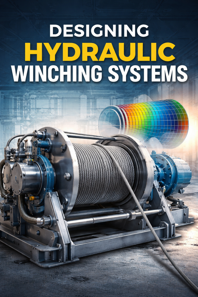
Hydraulic winching systems are critical components in heavy-duty industrial, marine, offshore, mining, and construction applications. From lifting and pulling operations on offshore platforms to towing, anchoring, and load handling in harsh environments, hydraulic winches must deliver high torque, precise control, and long-term reliability under extreme loads.
Designing a hydraulic winch is not simply about selecting a motor and drum. It requires a system-level engineering approach that integrates mechanical design, hydraulic circuit optimization, structural analysis, and safety validation. In modern engineering practice, Finite Element Analysis (FEA) plays a key role in verifying structural integrity, optimizing material usage, and preventing fatigue and failure.
This article provides a comprehensive engineering guide to hydraulic winch design, covering:
- Hydraulic winch system architecture
- Core hydraulic winch design formulas
- Structural and mechanical considerations
- FEA-based hydraulic winch design methodology
- Design diagrams and component interaction
- Practical insights aligned with a hydraulic winch design manual approach
Overview of a Hydraulic Winching System
A hydraulic winching system converts hydraulic energy into controlled mechanical pulling force. Unlike electric winches, hydraulic winches excel in continuous duty cycles, overload tolerance, and harsh environmental conditions.
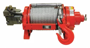
Main Components of a Hydraulic Winch
A typical hydraulic winch system includes:
- Hydraulic motor (axial piston or radial piston)
- Gearbox (planetary or spur)
- Winch drum
- Wire rope or synthetic rope
- Brake system (static and dynamic)
- Hydraulic control valves
- Structural frame and mounting base
- Bearings and shafts
Each component must be designed not in isolation, but as part of an integrated mechanical–hydraulic system.
Key Design Requirements for Hydraulic Winches
Before calculations or simulations begin, the following operational parameters must be clearly defined:
Load and Performance Requirements
- Rated line pull
- Maximum overload factor
- Line speed (loaded and unloaded)
- Duty cycle and operating hours
Environmental Conditions
- Marine or offshore exposure
- Temperature extremes
- Corrosive environments
- Shock and vibration loads
Safety and Compliance
- Industry standards (ISO, API, DNV, FEM)
- Emergency braking requirements
- Redundancy and fail-safe operation
These requirements directly influence hydraulic winch design formulas, material selection, and FEA assumptions.
Hydraulic Winch Design Formula Fundamentals
Accurate calculations form the backbone of reliable winch design. Below are the core equations used in engineering practice.
Line Pull Calculation
The required line pull determines motor torque and system pressure:
F=TdrdF = \frac{T_d}{r_d}F=rdTd
Where:
- F = Line pull (N)
- T_d = Drum torque (Nm)
- r_d = Effective drum radius (m)
Hydraulic Motor Torque
Hydraulic motor torque is calculated as:
Tm=ΔP×Vm×ηm2πT_m = \frac{ΔP \times V_m \times η_m}{2π}Tm=2πΔP×Vm×ηm
Where:
- ΔP = Pressure differential (Pa)
- V_m = Motor displacement (m³/rev)
- η_m = Mechanical efficiency
This equation is critical in hydraulic winch design manuals and directly affects motor selection.
Drum Speed and Line Speed
v=ωd×rdv = ω_d \times r_dv=ωd×rd
Where:
- v = Line speed (m/s)
- ω_d = Drum angular velocity (rad/s)
This relationship ensures the winch meets operational speed requirements without compromising torque capacity.
Brake Holding Capacity
The brake must hold at least 125–150% of the rated load:
Tb≥1.5×TdT_b ≥ 1.5 \times T_dTb≥1.5×Td
This safety margin is essential for static load holding and emergency stops.
Hydraulic Winch Design Diagram (System Layout)
A hydraulic winch design diagram typically illustrates:
- Hydraulic power supply (pump & reservoir)
- Directional control valves
- Pressure relief valves
- Hydraulic motor
- Gearbox
- Drum and brake assembly
- Structural frame and foundation
From an engineering perspective, the diagram clarifies load paths, pressure zones, and control logic. In advanced design workflows, this diagram becomes the basis for co-simulation between hydraulic and structural models.
Structural Design Considerations for Hydraulic Winches
Load Path Analysis
Structural loads flow through:
- Rope → drum → shaft → gearbox → frame → foundation
Misalignment or under-designed interfaces are common failure points.
Material Selection
- High-strength steels for drums and shafts
- Fatigue-resistant alloys for rotating components
- Corrosion-protected materials for marine environments
Fatigue and Cyclic Loading
Winches rarely fail due to single overload events. Most failures occur due to:
- Repeated load cycles
- Stress concentration at welds and keyways
- Bearing fatigue
This is where FEA-based hydraulic winch design becomes essential.
Hydraulic Winch Design Using FEA
Why FEA Is Critical in Winch Design
Finite Element Analysis enables engineers to:
- Identify stress concentrations
- Evaluate deformation under load
- Predict fatigue life
- Optimize weight without compromising safety
FEA is now standard practice in high-load hydraulic equipment design.
Typical FEA Studies for Hydraulic Winches
Drum Structural Analysis
- Radial pressure from wire rope layers
- Bending stresses due to uneven winding
- Local stress at flanges
Shaft and Bearing Analysis
- Combined torsional and bending loads
- Bearing reaction forces
- Deflection limits affecting gear meshing
Frame and Base Analysis
- Mounting bolt loads
- Dynamic amplification factors
- Foundation stiffness impact
FEA Load Cases to Consider
A professional hydraulic winch design manual typically includes:
- Rated load
- Overload condition (125–150%)
- Emergency stop load
- Fatigue load spectrum
- Transport and installation loads
Ignoring these load cases often leads to under-designed structures.
Hydraulic Winch Design Optimization Through Simulation
By integrating FEA early in the design process, engineers can:
- Reduce material costs
- Improve fatigue life
- Increase safety margins
- Shorten prototype testing cycles
Coupling hydraulic simulation (pressure, flow, transient response) with structural FEA provides a true system-level understanding of winch behavior.
Common Design Challenges and Engineering Solutions
Challenge 1: Excessive Drum Deformation
Solution: Increase flange stiffness, optimize wall thickness using FEA.
Challenge 2: Brake Overheating
Solution: Improve heat dissipation, validate braking torque through transient analysis.
Challenge 3: Frame Cracking
Solution: Redesign weld geometry and load paths based on stress contour results.
Best Practices from Hydraulic Winch Design Manuals
Professional manuals emphasize:
- Conservative safety factors
- Redundancy in braking systems
- Clear inspection and maintenance access
- Documentation of assumptions and load cases
FEA results should always be validated against hand calculations and empirical guidelines, not used blindly.
Applications of Hydraulic Winching Systems
Hydraulic winches are widely used in:
- Offshore oil & gas platforms
- Marine towing and anchoring
- Mining and heavy construction
- Wind turbine installation
- Industrial lifting systems
Each application imposes unique design constraints that must be reflected in hydraulic winch design formulas and simulations.
Conclusion
Designing hydraulic winching systems requires a multidisciplinary engineering approach that balances hydraulic performance, mechanical integrity, and structural safety. Traditional design formulas remain essential, but modern engineering demands FEA-based hydraulic winch design to meet increasing load, safety, and reliability requirements.
By combining:
- Accurate hydraulic calculations
- Clear system diagrams
- Robust structural design
- Advanced finite element analysis
engineers can deliver winching systems that perform reliably in the most demanding industrial environments.
For engineering teams and asset owners, investing in simulation-driven winch design is no longer optional — it is a competitive and safety necessity.