Steel Modeling in BIM: Fundamentals, Best Practices, and Real-World Applications
Introduction
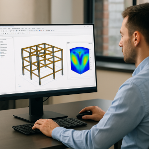
Steel structures remain one of the most widely used systems in industrial, commercial, and infrastructure projects. As projects become more complex, the need for accurate, coordinated, and fabrication-ready steel models is critical. Building Information Modeling (BIM) has transformed the way engineers, fabricators, and contractors work by enabling precise 3D modeling, automated documentation, better coordination, and reliable quantity outputs.
In this article, we explore the fundamentals of steel modeling in BIM, from LOD standards and parametric connections to clash detection, fabrication exports, and real case studies. Whether you work in industrial plants or bridge construction, these principles ensure accuracy, constructability, and project efficiency.
What Is Steel Modeling in BIM?
Steel modeling in BIM involves creating a detailed, data-rich 3D representation of a steel structure. Unlike traditional 2D drafting, BIM enables:
- Intelligent components with physical and analytical properties
- Automated generation of shop drawings
- Coordination with architecture and MEP systems
- Direct export to fabrication software
- Real-time clash detection
- Accurate scheduling and cost estimation
Tools such as Tekla Structures, Revit, Advance Steel, SDS/2, and Bentley STAAD/Pro + ProStructures are widely used for different stages of steel modeling depending on project needs.

Steel Modeling Fundamentals
A high-quality steel model must include:
- Columns, beams, trusses, braces
- Plates, stiffeners, angles
- Baseplates and anchor bolts
- Welds and bolts
- Brackets, ladders, handrails
- Secondary steel such as purlins and girts
These components form the foundation of a constructible BIM model that supports coordination and fabrication.
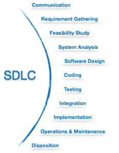
Level of Development (LOD) for Steel Models
The Level of Development (LOD) defines how much detail and information elements contain at various project stages.
LOD 100 – Conceptual
- Massing and approximate sizes
- Used for feasibility and early design
LOD 200 – Approximate Geometry
- Generic steel sections
- Used for coordination with architecture and MEP
LOD 300 – Accurate Geometry
- Specific profiles (IPE, HEA, UB, RHS, etc.)
- Member sizes fixed
- Supports structural analysis and coordination
LOD 350 – Detailed Connections
- Bolts, welds, plates, stiffeners, clip angles
- Member-to-member relationships
LOD 400 – Fabrication Level
- All components fully modeled
- Exact bolt sizes, spacing, weld lengths
- Ready for NC/DSTV export
LOD 500 – As-Built
- Final verified model after construction
Most steel fabrication projects require LOD 400, ensuring the model can be directly used for shop drawing creation and CNC output.
Parametric Families: Sections, Connections, Bolts
Parametric components are at the core of BIM. They allow repetitive steel elements to behave intelligently and automatically adjust based on design changes.
Steel Sections
- Standardized profiles: I-sections, H-sections, channels, angles, T-sections
- Country-specific standards: EN, AISC, BS, IS
- Custom profiles for special trusses or industrial steel
Connections
Parametric connections include:
- Moment and shear connections
- Gusset plate connections for bracing
- End-plate, fin-plate, splice connections
- Baseplates and anchor bolt layouts
- Welded vs bolted assemblies
Tools like Tekla’s Smart Components or Revit’s Connection Families help automate repeated connection types.
Bolts and Welds
- Bolt grades (8.8, 10.9)
- Bolt diameters and spacing rules
- Weld types: fillet, groove, flare, plug
- Automatic clash checks between bolts and plates
These parametric features significantly reduce manual drafting time and improve accuracy.
Coordination with MEP and Architectural Models
One of the major advantages of BIM is real-time coordination between disciplines.
Why Coordination Matters
Steel structures often clash with:
- Ducts
- Cable trays
- HVAC units
- Piping systems
- Architectural walls and ceilings
Coordination Workflow
- Receive updated MEP and architectural models.
- Link them into the steel model.
- Identify conflicts early.
- Revise steel framing or coordinate with the respective teams.
- Update shop-level details accordingly.
Proper coordination reduces RFIs, delays, and costly on-site rework.
Clash Detection and Constructability Reviews
Using software such as Navisworks, Solibri, or BIMCollab, steel models undergo clash detection to ensure constructability.
Common Clash Types
- Beam-to-duct collisions
- Bolts interfering with concrete reinforcement
- Inadequate access for installation
- Connection plates overlapping with MEP elements
- Tolerance issues during erection
Constructability Checks
Ensure:
- Safe lifting points
- Accessible bolt tightening zones
- Adequate space for welding
- Members can be transported and installed
These checks prevent costly fabrication revisions and site disruptions.
Export to Fabrication (NC/DSTV)
Fabrication-ready models must support automated CNC machining.
Common Export Formats
- NC/DSTV (.nc1) for cutting, drilling, and marking
- IFC for interoperability
- KISS files for fabrication management systems
Fabricators can directly send the exported files to machines such as:
- Beamlines
- Plate cutting machines
- Punching machines
- Drilling robots
This eliminates manual input errors and accelerates production.
Model-Based Quantity Takeoff & Scheduling
BIM steel models allow automated extraction of:
Quantities
- Steel weight per member
- Plate dimensions
- Bolt counts
- Weld lengths
- Paint and fireproofing areas
Scheduling
- Sequencing based on erection zones
- Fabrication batches
- Delivery order
- On-site installation schedule
Model-based QTO improves cost accuracy and supports contractors in planning.
Accuracy & Tolerances in Shop Models
Steel fabrication depends on strict tolerances. A high-quality BIM model must reflect these constraints:
- Hole tolerances
- Plate cut tolerances
- Member length tolerances
- Camber and sweep specifications
- Bolt spacing precision
Following industry standards such as AISC, EN 1090, BS 5950, or project-specific requirements ensures the model translates perfectly into fabrication.
Change Management and Revision Control
Projects evolve, and BIM must manage change efficiently.
Best Practices
- Maintain clear revision logs
- Cloud-based model history and versioning
- Create delta reports for fabricators
- Use color-coded comparison models
- Avoid working on outdated references
Effective change management reduces rework and maintains model integrity throughout the project lifecycle.
Quality Checks Before Issuing for Fabrication
Before releasing the model to fabrication shops, the following must be verified:
- All members connected correctly
- Bolt grades and diameters confirmed
- Plate thicknesses and dimensions validated
- No duplicate or floating elements
- Assembly numbering sequences correct
- Welds assigned properly
- NC files checked for errors
- Shop drawings reviewed for readability
A reliable QC process ensures smooth fabrication and prevents production delays.
Best Practices for Federated Models
Large industrial or infrastructure projects often use federated models.
Considerations
- Keep steel models lightweight by using worksets or model filters
- Divide the structure into logical zones (north, south, east, west)
- Use consistent naming conventions
- Follow a shared coordinate system
- Set up clash avoidance rules between disciplines
This ensures smooth model exchange between engineering, architectural, and MEP teams.
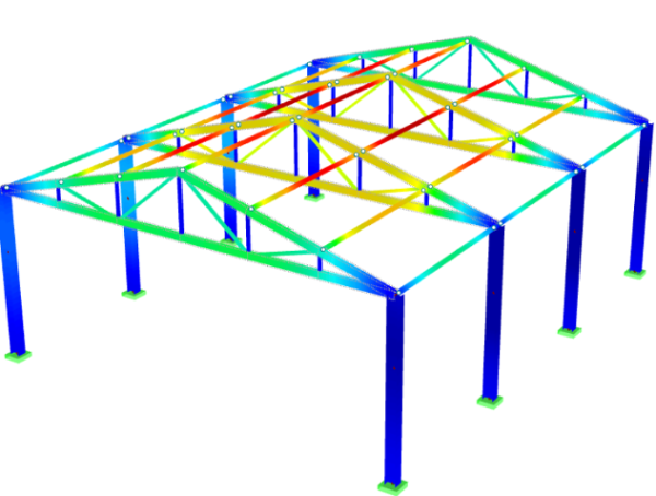
Case Studies: Industrial & Bridge Steel Modeling
Industrial Facility – Pipe Rack & Equipment Support
In industrial plants, steel modeling requires extreme accuracy due to heavy coordination with piping, electrical, and HVAC.
BIM enabled:
- LOD 400 fabrication-ready models
- Automated clash detection with pipes & trays
- Quick revision cycles
- Direct CNC exports for fabrication
- Zero site rework for steel structures
This reduced installation time by 20% and improved model reliability.
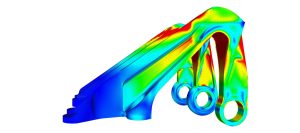
Steel Bridge Modeling
Bridge projects demand high precision due to complex geometries and curved steel members.
BIM supported:
- Parametric modeling of girders and stiffeners
- Exact camber and sweep modeling
- Clash avoidance with utilities running inside the bridge
- Fully detailed connection modeling for shop drawings
- Accurate quantity extraction for procurement
This enabled faster production and reliable assembly on site.
Conclusion
Steel modeling in BIM is now an essential part of modern engineering and construction. From LOD definitions and parametric connections to fabrication exports and constructability checks, every step impacts project success. When executed properly, BIM enhances accuracy, reduces risk, and supports smooth coordination across all project disciplines.
For industrial facilities, bridges, commercial buildings, or any steel-intensive project, a detailed and well-managed steel model ensures efficiency from design to fabrication and installation.
If you want Avesta Consulting to support your next project with high-precision steel modeling, BIM management, or clash detection services, we offer tailored solutions for fabrication shops, EPC contractors, and design engineering teams.
FAQ :
1. What is steel modeling in BIM?
Steel modeling in BIM is the process of creating a detailed, data-driven 3D model of steel structures, including beams, columns, connections, and bolts. It improves coordination, reduces errors, and enables direct fabrication exports such as NC/DSTV files.
2. What LOD level is required for steel fabrication?
For steel fabrication, LOD 400 is typically required. This level includes exact member dimensions, connections, bolts, welds, and all fabrication details needed for shop drawings and CNC processing.
3. What software is used for steel modeling?
Common tools include Tekla Structures, Advance Steel, Revit, SDS/2, and Bentley ProStructures. The choice depends on project size, complexity, and fabrication requirements.
4. How does clash detection help steel modeling?
Clash detection identifies conflicts between steel, MEP, and architectural elements. This prevents rework, reduces RFIs, improves constructability, and ensures installation sequences run smoothly.
5. What is NC/DSTV export in steel fabrication?
NC/DSTV files are machine-readable formats used for CNC beamlines, drilling, and cutting machines. They allow fabrication shops to produce steel components directly from the BIM model with zero manual data entry.
6. Why is coordination important between steel and MEP models?
Because ducts, pipes, and cable trays often conflict with steel beams or connections. Early coordination avoids delays, redesigns, and on-site modifications.
7. How accurate are quantity takeoffs from BIM steel models?
Model-based QTOs can reach 95–100% accuracy, as they are extracted from real geometric and parametric data—providing reliable steel tonnage, bolt counts, weld lengths, and plate details.
8. What quality checks are needed before issuing steel models for fabrication?
Checks include verifying connection details, bolt grades, plate sizes, member numbering, weld specifications, and clash-free assemblies. This ensures the model is fabrication-ready and error-free.
9. What are the benefits of using BIM for steel bridges or industrial structures?
BIM improves geometric accuracy, supports load path validation, provides better coordination with utilities, and speeds up fabrication. It also reduces project risk and installation time.
10. Can BIM steel models be used for scheduling?
Yes. BIM enables 4D scheduling, where steel elements are linked to the construction timeline, allowing planners to visualize erection sequences and optimize logistics.