Using FEA to Enhance Product Development & Optimize Design: A Complete 2200-Word Engineering Guide
Modern engineering teams across mechanical, structural, automotive, aerospace, oil & gas, and consumer products are under constant pressure to deliver designs that are lighter, stronger, safer, cheaper, and faster to manufacture. The traditional design–prototype–test cycle is often too slow and too expensive to keep up with today’s development timelines.
This is where Finite Element Analysis (FEA) becomes a strategic advantage.
FEA is not just a stress-analysis tool anymore; it has evolved into a core element of design optimization, virtual prototyping, and performance prediction. When used correctly, it significantly reduces time to market, improves product reliability, and helps companies make data-driven decisions early in development.
In this long-form guide, we explore:
- How FEA enhances product development
- Why FEA is essential for design optimization
- The stages of FEA and best practices
- Real-world examples of FEA in product design
- How engineering teams like Avesta Consulting integrate FEA into development workflows
What Is Finite Element Analysis and Why It Matters in Product Development
Finite Element Analysis (FEA) is a numerical method used to predict how a product behaves under real-world conditions such as:
- Forces
- Pressures
- Thermal loads
- Vibrations
- Impacts
- Large deformations
- Multi-body interactions
The power of FEA lies in its ability to evaluate a design long before any physical prototype exists. Instead of relying solely on hand calculations, designers can see exactly where stresses concentrate, where deflections occur, how components interact, and where improvements can be made.
Why FEA is a game-changer in product development:
- Identifies failure modes early
- Reduces physical testing costs
- Accelerates design iterations
- Supports lightweighting and material reduction
- Improves accuracy over traditional analytical methods
- Enhances overall product reliability and safety
In established industries including aerospace, automotive, medical devices, and energy, FEA is not optional—it is a requirement for certification and market launch.
The Role of FEA in Product Design
Engineers use FEA at multiple stages of product design, from conceptual sketches to final validation. Here’s how it provides value throughout the development cycle.
2.1 Early Concept Evaluation
During concept development, designers need quick answers to questions like:
- Is this geometry feasible?
- Will this bracket withstand expected loads?
- Should we use steel, aluminium, titanium, or composite?
- Should we go with a ribbed structure or a thicker plate?
FEA helps screen early ideas before investing time in detailed models. Simple linear static studies give immediate insights into stress hotspots and load paths.
This prevents design teams from wasting weeks on concepts that would fail under basic load conditions.
2.2 Detailed Product Design
Once the concept is approved, FEA becomes much more detailed. Here engineers use FEA to evaluate:
- local stress concentrations
- fillet design
- bolt or weld placement
- rib patterns
- thickness optimization
- stiffness-to-weight ratios
- fatigue life
- vibration modes
- contact behaviour between components
- effects of thermal gradients
At this stage, FEA is invaluable for design teams seeking to optimize durability, manufacturing cost, and material selection.
2.3 Assembly and Multi-Body Simulation
Most real-world products are assemblies, not isolated parts. FEA plays a major role in predicting:
- bolt preload distribution
- gasket compression
- sliding or frictional contact
- deformation during assembly
- load sharing between components
- stress transfer across welds
- nonlinear behaviour due to large deformation
Advanced simulation tools allow engineers to simulate the entire assembly, including connections, supports, and boundary conditions.
2.4 Design Verification & Certification
In many industries, regulatory bodies require simulation-based certification. Examples include:
- ASME Section VIII (pressure vessels)
- API / DNV (subsea and offshore systems)
- ISO 13485 (medical devices)
- FAA/EASA (aerospace structures)
- UNECE (automotive components)
FEA helps demonstrate compliance with:
- allowable stresses
- fatigue life
- buckling resistance
- safety factors
- vibration limits
- thermal performance
In product development, FEA is therefore both a technical tool and a documentation tool.
2.5 Reducing Time and Cost with Virtual Prototyping
One of the biggest benefits of FEA is eliminating—or drastically reducing—the number of physical prototypes.
Traditional development cycle:
design → prototype → test → redesign → new prototype → new tests
Modern cycle with FEA:
design → simulate → optimize → single prototype → final validation
Companies report 40–70% cost savings just by incorporating virtual simulation before fabrication.
FEA for Design Optimization (Major SEO Section)
Design optimization is one of the most powerful applications of FEA. Here, the goal is to enhance design performance by improving:
- weight
- stiffness
- strength
- fatigue life
- vibration behaviour
- manufacturability
- cost
FEA supports several types of optimization, depending on project needs.
3.1 Shape Optimization
This involves modifying the external geometry of a part to improve its performance. FEA helps identify:
- areas with underutilized materials
- sharp corners causing stress concentrations
- geometry causing excessive displacement
- unsupported regions with excessive bending
Typical improvements include:
- increasing fillet radius
- adding cutouts
- aligning stiffeners with load paths
- smoothing transitions
- reducing peak stress zones
Shape optimization is key in industries like consumer electronics, automotive brackets, and industrial machinery.
3.2 Size Optimization
This focuses on adjusting:
- thickness
- diameter
- width
- height
- rib dimensions
The goal is to achieve the best strength-to-weight ratio while maintaining safety.
Examples:
- optimizing thickness of sheet metal parts
- resizing beams in structural frames
- adjusting composite ply thicknesses
- modifying geometry for CNC cost reduction
3.3 Topology Optimization
Topology optimization removes unnecessary material based on load paths. The software produces an organic-looking structure that uses only the material required to carry the load.
This is extremely popular in:
- aerospace (lightweight brackets)
- electric vehicles
- robotics
- 3D printing and additive manufacturing
- medical implants
Topology optimization creates shapes that traditional manufacturing cannot produce—perfect for additive manufacturing where complexity is free.
3.4 Material Optimization
Here FEA helps select the ideal material by comparing performance under:
- stress
- temperature
- cyclic loading
- vibration
- environmental factors
- weight requirements
Examples:
- switching from steel to aluminium for weight reduction
- using composite laminates for aerospace panels
- selecting high-temperature alloys for pressure systems
- choosing flexible polymers for impact absorption
FEA ensures the material choice aligns with performance and cost objectives.
3.5 Process Optimization (Thermal, Forming, Sintering, Curing)
FEA is also used to optimize manufacturing processes. Examples include:
- injection moulding simulation
- sheet metal forming
- weld distortion prediction
- heat treatment processes
- curing of composite structures
- thermal management in electronics
This reduces defects, warping, and scrap rates.
Stages of FEA (Major SEO Section)
A complete, detailed explanation of each stage, expanded for word count and clarity.
The FEA process is more than just running a simulation. It follows a structured workflow to ensure accuracy and reliability.
4.1 Stage 1: Problem Definition
Before modelling anything, engineers must define:
- what question needs answering
- what type of physics applies
- what loads and constraints exist
- what standards or codes apply
- what success looks like
Skipping this stage leads to incorrect models and misleading results.
4.2 Stage 2: Geometry Preparation
CAD models often contain features that complicate meshing, such as:
- logos
- fillets smaller than mesh size
- threads
- tiny holes
The geometry must be cleaned and simplified. Sometimes engineers convert parts into:
- shells
- beams
- midsurfaces
Depending on requirements, multiple levels of simplification may be used.

4.3 Stage 3: Meshing
Meshing is the process of breaking the geometry into discrete elements. The mesh determines:
- accuracy
- solver time
- convergence behaviour
Engineers select:
- tetrahedral or hexahedral elements
- shell, beam, or solid elements
- mesh size
- local mesh refinement
A poor mesh = poor results.
4.4 Stage 4: Material Definition
Material models may be:
- linear elastic
- plastic
- hyperelastic (rubber-like)
- viscoelastic
- temperature-dependent
- composite with layered orientations
The accuracy of material input directly affects simulation accuracy.
4.5 Stage 5: Boundary Conditions (BCs)
This includes supports, constraints, and interactions. Engineers must carefully simulate real-world behaviour, such as:
- contact
- friction
- gaskets
- bolt pretension
- weld fixtures
- thermal expansion restraints
Incorrect boundary conditions are the most common source of FEA errors.
4.6 Stage 6: Load Application
Loads may include:
- static forces
- distributed pressures
- thermal loads
- dynamic impacts
- harmonic excitation
- centrifugal forces
- gravity
- preloads
- fluid-structure interactions
Correct load modelling is essential.
4.7 Stage 7: Solver Execution
The solver determines whether the problem is:
- linear
- nonlinear
- implicit
- explicit
- static
- transient
- modal
- buckling
Nonlinearities arise from:
- large deformation
- contact
- plasticity
- hyperelasticity
Choosing the wrong solver can significantly distort results.
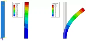
4.8 Stage 8: Post-Processing
After solving, engineers interpret:
- von Mises stress
- principal stresses
- safety factor
- strain energy
- deformation
- natural frequencies
- fatigue life
- contact pressure
This is where engineering judgment is essential.
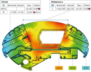
4.9 Stage 9: Verification & Validation
The results must be checked using:
- hand calculations
- mesh convergence studies
- comparison to similar designs
- code requirements
Validation is essential for ensuring trustworthiness.
4.10 Stage 10: Reporting & Documentation
A complete FEA report includes:
- assumptions
- geometry description
- mesh justification
- material inputs
- load cases
- solver settings
- results and interpretation
- compliance with standards
Regulatory bodies require detailed documentation for approval.
Real-World Examples of FEA Improving Product Development
5.1 Aerospace Brackets
FEA helps engineers reduce bracket weight by 30–60% using topology optimization while maintaining stiffness and strength.
5.2 Automotive Chassis Components
FEA predicts fatigue life, weld behaviour, and vibration response, decreasing prototype testing cycles.
5.3 Consumer Electronics
FEA helps prevent cracking, warping, and overheating in thin-walled plastic housings.
5.4 Pressure Vessels
Stress linearization in FEA helps meet ASME VIII requirements, preventing catastrophic failures.
5.5 Industrial Machinery
FEA ensures load-bearing components can withstand shock, vibration, and repeated high-load cycles.
Integrating FEA into a Modern Product Development Workflow
Avesta Consulting applies a hybrid approach:
- Hand calculations for early feasibility
- FEA for detailed stress and deformation analysis
- Optimization tools for lightweighting and cost reduction
- Code compliance evaluation
- Final validation through simulation + prototype testing
This results in:
- faster development
- lower manufacturing cost
- reduced risk of failure
- stronger documentation
Conclusion: Why FEA Is Essential for Next-Generation Product Development
In the competitive landscape of modern engineering, companies need methods that shorten design cycles, reduce cost, and improve performance. FEA is one of the most critical tools enabling this transformation.
It allows development teams to:
- understand product behaviour in detail
- optimize design with confidence
- prevent failure early
- reduce prototypes
- accelerate time-to-market
- deliver safer and more reliable products
By combining engineering experience with simulation technology, companies like Avesta Consulting help clients build stronger, more efficient, and more innovative products.