A Technical Guide for Reverse Engineering and Industrial Applications
Introduction
As products become more complex and development cycles shorter, 3D scanning technologies have become essential tools in modern engineering workflows. From legacy part reproduction to dimensional inspection and digital twin creation, 3D scanners for reverse engineering enable engineers to capture accurate geometric data from physical objects and convert it into usable digital models.
Among the most widely used 3D scanning methods are structured light scanning, laser scanning, and photogrammetry. Each technique is based on different physical principles and offers unique advantages, limitations, and accuracy levels. Selecting the wrong scanning method can lead to incomplete data, excessive noise, or insufficient accuracy for downstream CAD and simulation tasks.
This article provides a deep technical comparison of the main 3D scanning techniques used in reverse engineering. It explains what reverse engineering in 3D means, how different scanners work, and how to select the optimal technology for industrial, manufacturing, and engineering consulting applications.
What Is Reverse Engineering in 3D?
Reverse engineering in 3D is the process of capturing the geometry of an existing physical object and reconstructing it as a precise digital model. This digital representation is typically used for:
- CAD reconstruction
- Design modification and optimization
- Simulation and finite element analysis (FEA)
- Manufacturing replication
- Quality control and inspection
Unlike forward design, reverse engineering starts with a finished or semi-finished physical part, often without original CAD data or technical drawings.
Typical Use Cases for 3D Reverse Engineering
- Reproduction of discontinued or legacy parts
- Competitive benchmarking
- Tooling and mold redesign
- Failure analysis
- Digital archiving of complex geometries
At the core of any reverse engineering workflow lies the 3D scanner, which determines the accuracy, resolution, and reliability of the final digital model.
The Role of 3D Scanners in Reverse Engineering
A 3D scanner for reverse engineering captures spatial data from an object’s surface and generates a point cloud or polygon mesh. This raw data is then processed and converted into:
- NURBS surfaces
- Parametric CAD models
- Solid models for simulation and manufacturing
The quality of the reverse-engineered model depends directly on:
- Scanning accuracy
- Data density
- Surface coverage
- Noise level
Different scanning techniques address these requirements in different ways.
Overview of 3D Scanning Techniques
The three most commonly used 3D scanning techniques in engineering applications are:
- Structured Light Scanning
- Laser Scanning
- Photogrammetry
Each technique differs in:
- Data acquisition method
- Accuracy and resolution
- Environmental sensitivity
- Suitability for reverse engineering
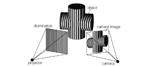
Structured Light Scanning
How Structured Light Scanners Work
Structured light scanners project a known pattern (typically stripes or grids) onto an object’s surface. Cameras capture the deformation of this pattern, and triangulation algorithms calculate the 3D coordinates of each point.
The system relies on:
- Projector-camera geometry
- Precise calibration
- Controlled lighting conditions
Advantages of Structured Light Scanning
- High surface detail and resolution
- Fast data acquisition
- Excellent for small to medium-sized parts
- Ideal for freeform and organic geometries
Limitations
- Sensitive to ambient lighting
- Reduced performance on reflective or transparent surfaces
- Limited working volume compared to laser trackers
Structured Light in Reverse Engineering
Structured light scanners are widely used for:
- Reverse engineering of plastic components
- Automotive interior parts
- Consumer product housings
- Medical and ergonomic designs
They are especially effective when surface detail and smooth curvature reconstruction are critical.
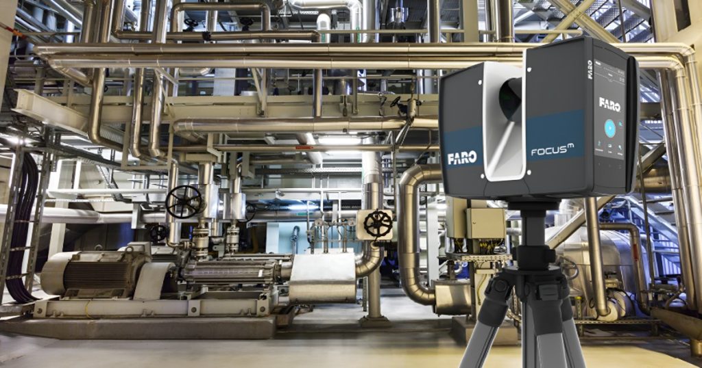
Laser Scanning Technology
How Laser Scanners Work
Laser scanners emit a laser beam onto the object’s surface and measure its reflection using either:
- Laser triangulation
- Time-of-flight (ToF)
- Phase-shift measurement
The reflected signal is used to calculate precise distance and position data.
Types of Laser Scanners
Laser Triangulation Scanners
- High accuracy and resolution
- Short to medium range
- Common in handheld and CMM-mounted scanners
Long-Range Laser Scanners (LiDAR)
- Large measurement volumes
- Lower resolution
- Used for buildings, plants, and infrastructure
Advantages of Laser Scanning
- High measurement accuracy
- Suitable for metallic and machined parts
- Less sensitive to ambient lighting
- Good performance in industrial environments
Limitations
- Slower scanning speed than structured light
- Data noise on highly reflective surfaces
- Higher system cost for metrology-grade scanners
Laser Scanning in Reverse Engineering
Laser scanners are preferred for:
- Mechanical components
- Engine blocks and housings
- Aerospace and automotive structures
- Dimensional verification tasks
When accuracy and tolerance compliance are critical, laser scanning often outperforms other techniques.
Photogrammetry
How Photogrammetry Works
Photogrammetry reconstructs 3D geometry from multiple 2D photographs taken at different angles. Specialized software identifies common features across images and calculates their spatial positions using structure-from-motion (SfM) algorithms.
Unlike active scanning systems, photogrammetry is a passive technique that does not emit light or lasers.
Advantages of Photogrammetry
- Cost-effective
- Scalable to very large objects
- Minimal hardware requirements
- Suitable for field and outdoor applications
Limitations
- Lower accuracy compared to structured light and laser scanning
- Highly dependent on image quality
- Requires good surface texture
- Time-consuming data processing
Photogrammetry in Reverse Engineering
Photogrammetry is often used for:
- Large industrial components
- Construction and civil structures
- Cultural heritage documentation
- Preliminary reverse engineering
For high-precision industrial reverse engineering, photogrammetry is typically combined with laser scanning or structured light systems.
Accuracy Considerations in 3D Reverse Engineering
Accuracy requirements depend on the final application:
- CAD reconstruction
- Simulation and FEA
- Manufacturing tolerance verification
Factors Affecting Accuracy
- Scanner technology
- Calibration quality
- Environmental conditions
- Operator experience
- Data processing algorithms
For reverse engineering, scanner accuracy must always exceed the required CAD tolerance to ensure reliable results.
Comparing 3D Scanning Techniques for Reverse Engineering
| Criterion | Structured Light | Laser Scanning | Photogrammetry |
| Accuracy | High | Very High | Medium |
| Resolution | Very High | High | Medium |
| Speed | Fast | Medium | Slow |
| Cost | Medium | High | Low |
| Large Objects | Limited | Good | Excellent |
From Scan Data to CAD Model
The reverse engineering workflow typically includes:
- Point cloud acquisition
- Noise filtering and alignment
- Mesh generation
- Surface reconstruction
- Parametric CAD modeling
The quality of each step depends heavily on the chosen 3D scanning technique.
Best Practices for Selecting a 3D Scanner for Reverse Engineering
- Define accuracy and tolerance requirements
- Consider part size and complexity
- Evaluate surface material and finish
- Assess environmental conditions
- Plan downstream CAD and simulation needs
Engineering consulting support is often critical for selecting and implementing the right solution.
The Role of Engineering Consulting in 3D Scanning Projects
Professional engineering consultants help organizations:
- Choose optimal scanning technology
- Define reverse engineering strategies
- Validate accuracy and uncertainty
- Integrate scan data into CAD, CAE, and PLM systems
At Avesta Consulting, advanced reverse engineering workflows are developed to ensure accuracy, efficiency, and compliance across industrial projects.
Conclusion
Understanding 3D scanning techniques is essential for successful reverse engineering. Structured light, laser scanning, and photogrammetry each offer unique strengths, and no single technology fits all applications.
By selecting the right 3D scanner for reverse engineering and applying best practices in data processing and validation, engineers can create accurate, reliable digital models that support design optimization, simulation, and manufacturing excellence.
As digital engineering continues to advance, 3D reverse engineering will remain a cornerstone of innovation, quality control, and industrial competitiveness.