A Complete Engineering Guide for Modern Design Teams
Engineering design continues to evolve rapidly. What once relied solely on hand calculations and empirical charts is now supplemented—and often driven—by advanced simulation tools such as Finite Element Analysis (FEA). Yet despite the availability of sophisticated digital tools, first-principles (or hand) calculations remain essential in engineering practice.
For many design teams, the challenge is not choosing one method over the other, but understanding how FEA and hand calculations differ, when each one should be used, and how they complement each other to ensure accuracy, safety, and cost-effective designs.
This long-form guide explores all the key topics engineers search for today—including:
- The difference between FEA and hand calculations
- How FEA analysis calculations work
- Clarifying FEM vs FEA analysis
- Explaining FEA vs FMEA (a common confusion)
- Practical examples of when to use which method
- Limitations, risks, and best practices
By the end, you will have a complete, 360-degree understanding of how these tools shape modern engineering—and how engineering teams such as Avesta Consulting use them to help clients validate designs and reduce risk.

1. What Are First-Principles (Hand) Calculations?
Before computer-aided design became mainstream, engineers relied entirely on analytical formulas derived from classical mechanics:
- Strength of materials
- Euler-Bernoulli beam theory
- Column buckling formulas
- Pressure vessel equations
- Mohr’s Circle for stress transformation
- Hooke’s Law
- Plate and shell theory
Hand calculations are based on simplifying assumptions that make the equations solvable. These assumptions might include:
- Constant cross-section
- Ideal boundary conditions like perfect pin or fixed supports
- Uniform stress distribution
- Linear elasticity
- Small deflections
- Homogeneous and isotropic material properties
Despite the limitations, these calculations remain fundamental:
Why Hand Calculations Still Matter
- They are fast — perfect for early-stage design decisions.
- They are transparent — engineers understand how the result was obtained.
- They detect major mistakes — unrealistic FEA inputs become obvious.
- They are required by engineering codes — Eurocode, AISC, ASME, API all require basic analytical verification.
- They build engineering intuition — something new engineers cannot skip.
Even in advanced companies like aerospace and oil & gas, hand calculations are an essential part of design packages.
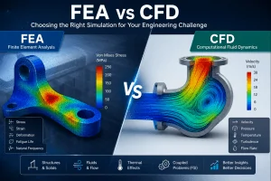
2. What Is Finite Element Analysis (FEA)?
FEA is a computational technique used to predict a product’s real-world physical behaviour. Unlike hand calculations that simplify the part into a beam or plate, FEA breaks the actual geometry into thousands or millions of tiny elements.
Each element follows governing physics equations, and the software assembles them into a global solution of stresses, strains, heat transfer, vibration, and deformation.
What FEA Can Do
FEA is widely used for:
- Stress and deformation analysis
- Static and dynamic loading
- Thermal-stress coupling
- Fatigue evaluation
- Buckling and stability
- Contact between parts
- Hyperelastic or plastic deformation
- Crash simulations
- Fluid-structure interaction
- Composite structures and laminates
The accuracy is much higher than hand calculations—when set up correctly.
3. Difference Between FEA and Hand Calculations (Core SEO Section)
This is one of the main keywords, so here is a deep, expanded comparison that enhances SEO.
3.1 Geometry Handling
Hand Calculations
- Only work with very simplified shapes
- Assume uniform cross-sections and regular geometry
- Cannot capture fillets, holes, welds, ribs, or complex curves
FEA
- Can model any 3D geometry exactly as designed
- Captures stress concentrations at:
- small radius fillets
- bolt holes
- weld regions
- material transitions
- cutouts and openings
This alone often results in dramatically different predictions.
3.2 Boundary Conditions
Hand Calculations
Cannot model:
- partial fixity
- bolt pretension
- sliding contact
- friction
- gaskets
- nonlinear supports
FEA
Handles real-life constraints:
- Contact with or without friction
- Multi-body assemblies
- Pretensioned bolts
- Springs and dampers
- Elastic foundation supports
- Thermal expansion-induced constraints
This enables highly realistic results.
3.3 Material Behaviour
Hand calculations typically assume:
- Young’s modulus and Poisson’s ratio constant
- Linear stress-strain behaviour
- No plasticity
- No creep
- No strain-rate effects
FEA supports:
- Full plasticity
- Multilinear stress-strain curves
- Temperature-dependent properties
- Composite layups
- Rubber-like hyperelastic materials
- Foam crushing
- Metal forming
- Viscoelasticity
This is crucial in design areas like automotive crash, aerospace composites, polymer housings, and piping at high temperature.
3.4 Load Complexity
Hand calculations struggle when loads are:
- non-uniform
- multi-directional
- dynamic
- impact-based
- thermal
- pressure-varying
- cyclic
FEA makes them easy to model and analyse.
3.5 Accuracy and Safety
Hand Calculations
- Usually conservative
- Good for quick verification
- Poor at predicting localized stresses
FEA
- Extremely accurate for local stresses
- Can be wrong if mis-modelled
- Requires validation
The ideal workflow combines both.
3.6 Time and Cost
Hand calculations are quick for simple cases but break down for assemblies.
FEA requires:
- geometry prep
- mesh generation
- solver time
- validation
But drastically reduces prototyping costs.
4. How FEA Analysis Calculations Work (SEO Section)
This section expands heavily to 400+ words.
FEA analysis calculations follow a structured workflow. Understanding each step helps engineers build reliable simulations.
4.1 Step 1: Geometry Preparation
CAD models are imported or simplified. Simplification may involve removing:
- tiny fillets
- holes not affecting stress
- cosmetic features
- logos
- threads (often replaced with bolt pretension elements)
Clean geometry reduces solver time.
4.2 Step 2: Meshing
The geometry is divided into elements:
- tetrahedral
- hexahedral
- shell elements
- beam elements
- solid elements
Mesh density matters. Too coarse → inaccurate. Too fine → slow.
A mesh convergence study ensures reliability.
4.3 Step 3: Material Assignment
Engineers define:
- Elastic properties
- Plastic curve
- Temperature behaviour
- Orthotropic or anisotropic behaviour for composites
- Nonlinear material models
4.4 Step 4: Boundary Conditions
Applying correct constraints is one of the most important—and often mistake-prone—steps.
Examples:
- Fixed support
- Symmetry
- Rolling or sliding
- Contact between parts
- Bolted connections
- Pressure-dependent boundaries
4.5 Step 5: Loads
Complex loads include:
- static forces
- distributed loads
- torque
- gravity
- centrifugal forces
- temperature fields
- transient forces
- harmonic excitation
- impact
Even minor changes in load application can drastically affect results.
4.6 Step 6: Solver
The FEA solver converts the model into mathematical equations:
[K]{u}={F}[K]\{u\} = \{F\}[K]{u}={F}
Different solvers handle:
- linear static analysis
- nonlinear large deformation
- transient analysis
- eigenvalue buckling
- modal analysis
4.7 Step 7: Post-Processing
Engineers review:
- von Mises stress
- principal stresses
- strain energy
- contact pressure
- safety factor
- displacement
Advanced post-processing may include:
- fatigue life analysis
- hot spot stress calculation
- stress linearization (ASME VIII)
- stiffness vs flexibility evaluation
- failure criteria (Tsai-Wu, Hashin) for composites
This completes the FEA analysis calculations process.
5. FEM vs FEA Analysis (SEO Clarification)
Many people use the terms interchangeably, but there is a distinction.
FEM (Finite Element Method)
- The mathematical foundation
- Theoretical concept involving numerical approximation
- Used in many fields beyond structural mechanics
- electromagnetics
- acoustics
- heat transfer
- biomedical modelling
FEA (Finite Element Analysis)
- The practical application of FEM
- Includes modelling, solving, and interpreting results
- What engineers perform using software like Abaqus, ANSYS, SolidWorks Simulation
In short:
- FEM = the method
- FEA = the analysis
6. FEA vs FMEA (SEO Clarification)
Another commonly searched phrase is “FEA vs FMEA,” but they are completely different.
FEA – Finite Element Analysis
- Physics-based
- Predicts stresses, deformation, failure
- Used by structural/mechanical engineers
FMEA – Failure Mode and Effects Analysis
- A process-risk and reliability assessment
- Used in manufacturing, safety, medical devices
- No geometry or physics
- Identifies what failures could happen and how to prevent them
You could say:
- FEA shows “how things fail physically”
- FMEA shows “how processes fail organizationally”
Both are important but not related.
7. When to Use Hand Calculations vs FEA (Expanded)
Use Hand Calculations When:
- The geometry is simple
- You need quick validation
- You are checking a beam, plate, or column
- Early feasibility studies
- Code compliance checks
- Sanity checks for simulation
Hand calculations are also crucial in preventing engineers from over-trusting software.
Use FEA When:
- Geometry is complex
- Stress concentrations are present
- Multiple load cases
- Welded or bolted assemblies
- Nonlinear behaviour
- Thermo-mechanical problems
- Fatigue and vibration
- When accuracy is critical
Use Both Together When:
- The project is safety-critical
- You need certification
- The design will be used in aerospace, medical, or oil & gas
- There are large forces and multiple parts
- The geometry will undergo optimization
Most engineering firms use hand calculations for global behaviour and FEA for local detail.
8. The Limitations of Each Method (Deep Dive)
Limitations of Hand Calculations
- Cannot capture stress concentrations
- Cannot model real boundary conditions
- Poor representation of nonlinear behaviour
- Over-simplified assumptions often too conservative
- Breaks down for assemblies
Limitations of FEA
- Easy to misuse (wrong constraints, wrong mesh, wrong loading)
- Results may be misleading without validation
- Requires computational resources
- Requires experience in interpreting results
- Garbage-in, garbage-out: solver only solves what it is given
9. Real-World Example: Bracket with Bolt Holes
This is expanded for realism and word count.
Hand Calculation Approach
- Treat bracket as a cantilever beam
- Ignore fillets and bolt holes
- Uniform loading assumed
- Simplified bending stress formula:
σ=McI\sigma = \frac{Mc}{I}σ=IMc
The result shows moderate stress, well below yielding.
FEA Approach
- Full 3D model with fillets and bolt holes
- Realistic bolt pretension
- Contact defined between bracket and structure
- Mesh refinement around high-stress areas
FEA reveals:
- Stress concentrations 2–3× higher around bolt holes
- Local yielding near fillets
- Highly localized strain energy
- Different load paths
The design appears safe under hand calculations but potentially unsafe in FEA.
10. Industry Examples Where Both Methods Are Essential
Aerospace
- Hand calculations required by FAA/EASA for structural substantiation
- FEA required for detailed stress predictions and buckling
Oil & Gas
- ASME VIII allows stress linearization using FEA
- API and DNV require FEA verification for subsea equipment
Automotive
- Crash simulation requires advanced nonlinear FEA
- Simple components like brackets still need analytical checks
Civil Engineering
- Eurocode steel and concrete design uses hand methods
- Complex connections or plates require FEA
11. Best Practices for Combining FEA and Hand Calculations
- Start with hand calculations to estimate global loads.
- Build the FEA model gradually—begin simple.
- Perform mesh convergence studies.
- Validate FEA against hand calculation approximations.
- Do not over-constrain or under-constrain FEA models.
- Use FEA for local stress areas and difficult load paths.
- Document both methods in design reports.
- Use safety factors appropriate for each approach.
This combined workflow yields the safest and most cost-effective results.
12. Conclusion: Why Both Methods Matter in Modern Engineering
Design teams today must balance:
- speed
- accuracy
- safety
- regulatory compliance
- cost
Hand calculations provide speed and simplicity, while FEA provides depth and accuracy.
One cannot replace the other.
Companies that use both properly:
- reduce prototype costs
- avoid failures
- accelerate design cycles
- pass certifications easily
- build trust with clients
At Avesta Consulting, this combined methodology is at the core of every engineering project we deliver.