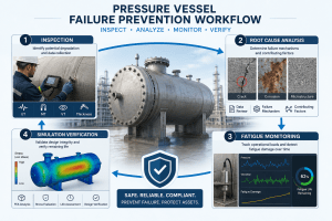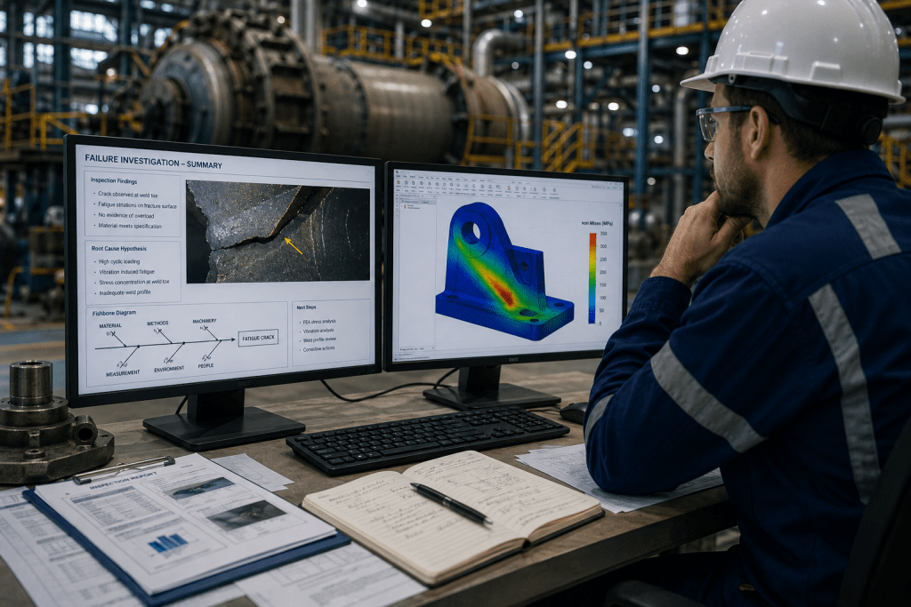
Root Cause Failure Analysis, commonly known as RCFA, is one of the most important investigation methods used in engineering, maintenance, reliability, manufacturing, mining, oil and gas, power generation, infrastructure, and industrial operations. When equipment fails, production stops, safety risks increase, and repair costs rise. However, the most expensive mistake is not the failure itself. The most expensive mistake is fixing the visible damage without understanding why the failure happened.
This is where RCFA tools become essential.
RCFA tools help engineers move from assumption to evidence. They create a structured path for identifying what failed, how it failed, why it failed, and what must change to prevent recurrence. Some RCFA tools are simple and team-based, such as 5 Whys and Fishbone diagrams. Others are technical and engineering-driven, such as fracture mechanics, fatigue analysis, finite element analysis, material testing, and metallurgical investigation.
The best RCFA investigations rarely depend on one method alone. A simple production issue may be solved using 5 Whys and Pareto analysis. A repeated structural crack, pressure vessel failure, rotating equipment breakdown, or weld fracture may require a combination of inspection, engineering simulation, material analysis, fatigue assessment, and root cause logic.
This article explains the most common RCFA tools, how engineers select them, where each method is useful, and how multiple tools can be combined into a reliable investigation workflow.
Why RCFA Tools Matter
RCFA tools matter because failures are rarely caused by one isolated factor. A bearing may fail because of lubrication loss, but the deeper cause may be poor maintenance planning, incorrect lubricant selection, contamination, misalignment, excessive vibration, inadequate training, or a design condition that was never properly verified. A cracked weld may appear to be a welding defect, but the true cause may involve fatigue loading, thermal stress, poor joint geometry, residual stress, corrosion, or operating conditions outside the original design basis.
Without structured tools, investigations can become subjective. Teams may jump to conclusions based on experience, assumptions, or pressure to restart production quickly. This often leads to temporary fixes rather than permanent solutions.
RCFA tools help teams:
Identify causes based on evidence rather than opinion.
Organize complex information into a clear structure.
Separate symptoms from contributing causes and root causes.
Avoid focusing only on human error or component replacement.
Compare technical, operational, maintenance, and organizational factors.
Validate findings before corrective actions are implemented.
Create corrective actions that prevent recurrence.
For engineering organizations, RCFA tools also improve communication. Failure investigations often involve several groups: operations, maintenance, design engineers, inspectors, reliability engineers, vendors, management, and sometimes regulators. A clear tool-based process helps everyone understand how conclusions were reached and why certain actions are recommended.
How Engineers Select RCFA Tools
Selecting the right RCFA tool depends on the nature of the failure, the complexity of the system, the availability of data, and the level of technical certainty required. Not every failure requires advanced simulation or laboratory testing. At the same time, not every failure can be solved with a simple 5 Whys session.
Engineers usually consider several questions before choosing RCFA tools:
What failed?
Was the failure mechanical, structural, electrical, material-related, process-related, or operational?
Was it a one-time event or a recurring failure?
Is there enough data to reconstruct the event?
Is the failure safety-critical or production-critical?
Does the failure involve fracture, fatigue, corrosion, overheating, wear, vibration, or deformation?
Do we need to prove the physical failure mechanism?
Do we need to assess remaining life or risk of recurrence?
Could the same failure occur in similar equipment?
For simple failures with clear evidence, a basic tool may be enough. For example, if a pump stopped because a filter was blocked, and the blocked filter was caused by a missed maintenance task, a structured 5 Whys analysis may identify the issue and corrective action.
For complex engineering failures, tool selection must go deeper. If a conveyor structure cracks repeatedly, a Fishbone diagram may help organize possible causes, but it will not prove whether the crack resulted from fatigue, poor weld geometry, resonance, overload, corrosion, or design deficiency. In that case, the RCFA may require inspection, vibration measurement, fatigue analysis, FEA, material testing, and a final logic-based root cause review.
The goal is not to use as many tools as possible. The goal is to use the right tools to reach a defensible conclusion.
The Most Common RCFA Tools
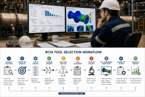
The most common RCFA tools include both general problem-solving methods and technical engineering methods. Each tool has strengths and limitations. The key is understanding when each tool is appropriate.
5 Whys Analysis
5 Whys Analysis is one of the simplest and most widely used RCFA tools. It involves asking “why?” repeatedly until the investigation reaches an underlying cause that can be addressed through corrective action.
For example:
Problem: A motor failed.
Why did the motor fail?
Because it overheated.
Why did it overheat?
Because the cooling fan was not working.
Why was the cooling fan not working?
Because the fan belt had broken.
Why did the fan belt break?
Because it was worn and had not been replaced.
Why was it not replaced?
Because the preventive maintenance schedule did not include inspection of that belt.
In this example, replacing the motor or fan belt alone would not solve the root cause. The corrective action should include updating the maintenance schedule, assigning inspection responsibility, and verifying that similar equipment has the same risk.
The strength of 5 Whys is simplicity. It is easy to teach, quick to apply, and useful for straightforward problems. It encourages teams to look beyond the first visible cause.
However, 5 Whys also has limitations. It can become too linear for complex failures. It may follow only one cause path, even when several contributing causes exist. The quality of the result depends heavily on the knowledge and objectivity of the people involved. If the team starts with the wrong assumption, the analysis can move in the wrong direction.
5 Whys is best used for simple failures or as an early-stage tool before applying deeper methods.
Fishbone Diagram (Ishikawa Diagram)
The Fishbone Diagram, also known as the Ishikawa Diagram or cause-and-effect diagram, is used to organize possible causes into categories. It is especially useful when a failure may have multiple contributing factors.
Common categories include:
People
Methods
Machines
Materials
Environment
Measurement
Management
In engineering investigations, the categories can be adjusted to suit the asset. For a mechanical failure, the team might use categories such as design, material, fabrication, operation, maintenance, loading, environment, inspection, and controls.
For example, if a pressure vessel nozzle crack is being investigated, a Fishbone diagram can help list potential causes under several categories:
Design: stress concentration, inadequate nozzle reinforcement, poor support arrangement.
Material: incorrect grade, low toughness, susceptibility to cracking.
Fabrication: weld defects, residual stress, poor heat treatment.
Operation: pressure cycling, thermal shock, overpressure events.
Environment: corrosion, chloride exposure, hydrogen service.
Inspection: missed crack indications, insufficient NDT coverage.
The advantage of a Fishbone diagram is that it prevents the team from focusing too narrowly on one possible cause. It encourages a broad view of the system.
The limitation is that it does not prove the cause. It is an organizing tool, not a verification tool. After possible causes are listed, engineers must still collect evidence, test assumptions, and eliminate unsupported causes.
Fishbone diagrams are useful in the early and middle stages of RCFA, especially for team workshops and brainstorming.
Fault Tree Analysis (FTA)
Fault Tree Analysis, or FTA, is a logical method used to show how combinations of events can lead to a top failure event. It starts with the failure at the top and works downward through logical branches.
FTA is particularly useful for complex systems where failure can occur through different pathways. It uses logic gates such as AND and OR to show whether multiple conditions must occur together or whether any one condition can cause the event.
For example, a pressure relief failure might be caused by:
Relief valve blocked.
Relief valve undersized.
Relief valve set pressure incorrect.
Isolation valve closed.
Control system failed.
Fire case not considered.
Operator response delayed.
FTA helps engineers understand how different failures combine. It is valuable for safety-critical assets, high-risk systems, process plants, control systems, and equipment where multiple safeguards are involved.
The strength of FTA is that it supports logical thinking and can be used for qualitative or quantitative analysis. If probability data is available, FTA can help estimate risk.
The limitation is that it requires a well-defined top event and accurate system knowledge. If the fault tree is built poorly, it may miss important failure paths.
FTA is best used for complex failures, safety-related investigations, overpressure events, control system failures, and incidents involving multiple barriers.
Failure Mode and Effects Analysis (FMEA)
Failure Mode and Effects Analysis, or FMEA, is a proactive reliability tool often used during design, process planning, maintenance planning, and risk assessment. In RCFA, FMEA is useful because it helps compare actual failures against expected or previously identified failure modes.
FMEA examines:
Potential failure modes.
Potential effects of each failure.
Possible causes.
Existing controls.
Severity.
Occurrence.
Detection.
Recommended actions.
In an RCFA investigation, FMEA can be used in two ways. First, engineers can check whether the failed component or process had already been assessed in a previous FMEA. If the failure mode was known but not controlled effectively, the root cause may involve weak risk controls. Second, the RCFA findings can be used to update the FMEA so that future risks are better managed.
For example, if a gearbox repeatedly fails due to bearing contamination, the FMEA may need to be updated to include contamination control, seal inspection, oil analysis, breather selection, storage conditions, and maintenance procedures.
The strength of FMEA is that it connects failure learning to prevention. It helps organizations move from reactive repairs to proactive reliability planning.
The limitation is that FMEA depends on assumptions and team knowledge. It may miss unknown failure modes, especially if the team lacks field experience or does not update the document after real failures.
FMEA is best used for proactive prevention, risk prioritization, and converting RCFA findings into long-term reliability controls.
Event and Causal Factor Analysis
Event and Causal Factor Analysis is used to reconstruct what happened before, during, and after an incident. It places events in chronological order and identifies the conditions that influenced each step.
This tool is especially useful when timing matters. Many failures do not occur instantly. They develop through a sequence of decisions, process deviations, equipment conditions, alarms, maintenance activities, inspections, and operating changes.
For example, a boiler tube failure may involve:
A change in water chemistry.
Delayed response to abnormal readings.
Scale formation.
Local overheating.
Tube wall thinning.
Tube rupture.
Emergency shutdown.
By mapping the timeline, engineers can see how conditions developed and where intervention could have prevented the failure.
The strength of Event and Causal Factor Analysis is that it reveals the sequence of contributing conditions. It is useful for incidents involving human actions, procedures, alarms, maintenance timing, operating changes, and process upsets.
The limitation is that it requires accurate records. If logs, data, and witness statements are incomplete, the timeline may contain uncertainty.
This tool is best used for process incidents, safety events, operational failures, and multi-step breakdowns.
Pareto Analysis
Pareto Analysis is based on the principle that a small number of causes often account for a large portion of failures or losses. It helps teams prioritize where to focus investigation and improvement efforts.
In RCFA, Pareto charts are commonly used to analyze:
Most frequent equipment failures.
Highest downtime contributors.
Most expensive failure types.
Recurring defect categories.
Most common alarm causes.
Maintenance cost drivers.
For example, a plant may have hundreds of maintenance events per year. Pareto Analysis may show that 70% of unplanned downtime comes from only five equipment types. This helps engineers focus RCFA efforts on the failures that matter most.
The strength of Pareto Analysis is prioritization. It prevents teams from spending too much time on low-impact issues while major failure drivers continue to repeat.
The limitation is that Pareto Analysis identifies patterns, not causes. It tells the team where to investigate, but not why the failures occur.
Pareto Analysis is best used at the beginning of reliability improvement programs or when deciding which failures deserve detailed RCFA.
Advanced Engineering Tools Used in RCFA
Simple RCFA tools are valuable, but engineering failures often require technical verification. When components crack, deform, wear, corrode, overheat, or fail under cyclic loads, engineers must understand the physical mechanism of failure.
Advanced engineering tools provide the evidence required to confirm or reject root cause hypotheses.
Fracture Mechanics
Fracture mechanics is used when cracks are present or when crack growth is a major concern. It helps engineers evaluate whether a crack could grow under the applied stress conditions and whether the component is safe to continue operating.
Fracture mechanics is particularly useful for:
Pressure vessels.
Pipelines.
Welded structures.
Rotating equipment.
Mining machinery.
Cranes and lifting equipment.
Structural components.
Components with known cracks or defects.
In RCFA, fracture mechanics helps answer important questions:
Did the crack grow gradually or fail suddenly?
Was the crack caused by fatigue, overload, stress corrosion cracking, or brittle fracture?
How critical was the crack size?
Could the crack have been detected earlier?
What stress level was required for failure?
Is similar equipment at risk?
The strength of fracture mechanics is that it connects crack size, material toughness, stress level, and failure risk. It supports engineering decisions about repair, replacement, inspection intervals, and remaining life.
Its limitation is that it requires good data, including crack dimensions, material properties, stress conditions, and loading history. Without accurate inputs, conclusions may be uncertain.
Fatigue Analysis
Fatigue Analysis is used when repeated loading causes progressive damage. A component can fail by fatigue even when the stress is below its static strength. This makes fatigue one of the most important mechanisms in rotating machinery, vibrating equipment, welded structures, pressure equipment, and cyclic process systems.
Fatigue failure may result from:
Pressure cycling.
Thermal cycling.
Vibration.
Repeated start-ups and shutdowns.
Flow-induced vibration.
Misalignment.
Resonance.
Cyclic structural loading.
Poor weld detail.
In RCFA, fatigue analysis helps determine whether the observed crack or failure is consistent with the number and magnitude of stress cycles experienced by the equipment.
For example, if a vibrating screen beam cracks repeatedly, fatigue analysis can help determine whether the stress range is too high, whether resonance is present, whether the weld detail is unsuitable, or whether the operating duty is more severe than expected.
The strength of fatigue analysis is that it links real operating conditions to failure life. It is highly valuable for repeated cracking and recurring structural failures.
The limitation is that fatigue analysis requires loading data. Without vibration measurements, cycle counts, stress ranges, or operating history, the analysis may rely on assumptions.
Finite Element Analysis (FEA)
Finite Element Analysis, or FEA, is an engineering simulation method used to calculate stress, strain, deformation, natural frequencies, thermal gradients, buckling risk, and fatigue-critical locations. In RCFA, FEA is used to verify whether the physical evidence matches the proposed failure mechanism.
FEA can help answer questions such as:
Where are the highest stresses located?
Is the failure location consistent with the stress concentration?
Did the design have insufficient strength?
Are nozzle loads, weld details, supports, or attachments causing local stress?
Could thermal gradients cause cracking?
Could vibration or resonance explain the failure?
Would a proposed design modification reduce stress?
FEA is especially useful when the failure is structural, mechanical, thermal, or vibration-related. It allows engineers to compare the original design, the failed condition, and the proposed repair or modification.
The strength of FEA is that it visualizes and quantifies engineering behaviour. It helps move the investigation from opinion to evidence.
The limitation is that FEA must be built carefully. Incorrect boundary conditions, loads, material properties, mesh quality, or assumptions can produce misleading results. Simulation should support evidence, not replace field inspection and engineering judgment.
Material Testing and Metallurgical Analysis
Material testing and metallurgical analysis are essential when the failure may involve material defects, incorrect material grade, heat treatment issues, corrosion, embrittlement, weld defects, or manufacturing problems.
Common tests include:
Chemical composition analysis.
Hardness testing.
Tensile testing.
Impact testing.
Microscopy.
Fractography.
Corrosion product analysis.
Weld examination.
Microstructure evaluation.
Material testing can confirm whether the material met specification, whether the weld was properly produced, whether the material became brittle, whether corrosion contributed, or whether the failure surface shows fatigue, overload, hydrogen damage, or stress corrosion cracking.
The strength of material testing is direct physical evidence. It helps confirm what happened at the material level.
The limitation is that laboratory results must be interpreted in context. Finding a crack or defect does not automatically prove root cause. Engineers must connect material evidence with design, operation, inspection history, and loading conditions.
Comparison of Common RCFA Tools
Each RCFA tool serves a different purpose. Selecting the right method depends on the question the investigation needs to answer.
5 Whys is best for simple, direct cause chains. It is fast and easy but may oversimplify complex failures.
Fishbone Diagram is best for brainstorming and organizing multiple possible causes. It is useful for team discussion but does not prove the cause.
Fault Tree Analysis is best for complex systems and safety-critical events. It shows logical failure paths but requires detailed system knowledge.
FMEA is best for
prevention and risk prioritization. It helps update reliability programs but depends on assumptions and regular review.
Event and Causal Factor Analysis is best for timeline-based incidents. It reveals event sequences but requires accurate records.
Pareto Analysis is best for prioritizing repeated failures. It identifies major problem areas but does not explain root causes.
Fracture Mechanics is best for crack assessment and remaining life decisions. It requires crack, stress, and material data.
Fatigue Analysis is best for cyclic loading and repeated cracking. It requires operating cycle or vibration data.
FEA is best for stress, deformation, vibration, and thermal verification. It requires accurate modelling and engineering interpretation.
Material Testing is best for confirming material condition, defects, fracture surfaces, and metallurgical mechanisms. It requires specialist interpretation and connection to operating context.
Which RCFA Tool Should You Use?
The right RCFA tool depends on the failure type and investigation objective.
Use 5 Whys when the issue is simple, the event is well understood, and the team needs a fast structured method.
Use a Fishbone Diagram when there are many possible causes and the team needs to organize ideas before testing them.
Use Fault Tree Analysis when the failure involves multiple barriers, safeguards, logic paths, or system interactions.
Use FMEA when the goal is to prevent future failures, update risk controls, or improve design and maintenance planning.
Use Event and Causal Factor Analysis when the sequence of events matters and the investigation must understand how conditions developed over time.
Use Pareto Analysis when many failures are occurring and the team needs to decide where detailed RCFA should be focused first.
Use Fracture Mechanics when cracks, crack growth, fracture toughness, or remaining life are important.
Use Fatigue Analysis when repeated loading, vibration, cyclic operation, or recurring cracks are involved.
Use FEA when stress distribution, deformation, thermal gradients, vibration modes, or design modification verification are required.
Use Material Testing and Metallurgical Analysis when the failure may involve material defects, weld quality, corrosion, embrittlement, or microstructural changes.
In practice, the best tool is often a combination of several methods.
Combining Multiple RCFA Methods
A strong RCFA rarely relies on one tool from start to finish. Most successful investigations combine simple logic tools with technical verification.
For example, a cracked support bracket on mining equipment may be investigated using:
Pareto Analysis to confirm that bracket failures are recurring and high-impact.
Visual inspection and NDT to locate cracks.
Fishbone Diagram to identify possible causes.
Event and Causal Factor Analysis to review operating history and maintenance events.
FEA to determine stress concentration and vibration sensitivity.
Fatigue Analysis to assess cyclic loading and expected life.
Material Testing to confirm weld and material condition.
5 Whys to trace the verified cause back to maintenance, design, or operational controls.
Corrective action verification to confirm the solution prevents recurrence.
This combination creates a stronger conclusion than any single tool could provide. The logic tools structure the investigation. The engineering tools prove or reject technical hypotheses. The final corrective actions address the root cause, not only the visible failure.
Example Investigation Workflow
A practical RCFA workflow may follow these steps:
Step 1: Define the problem clearly.
Describe what failed, where it failed, when it failed, and what impact it caused. Avoid vague statements such as “equipment failure.” Use specific wording such as “fatigue crack at the weld toe of the left-side support bracket after 4,000 operating hours.”
Step 2: Preserve evidence.
Before repair or cleaning, collect photographs, failed parts, operating data, inspection reports, maintenance records, drawings, and witness information.
Step 3: Identify immediate causes.
Determine the direct technical issue, such as crack, wear, corrosion, overheating, deformation, misalignment, leakage, or overload.
Step 4: Use a Fishbone Diagram.
Organize possible causes under categories such as design, material, fabrication, operation, maintenance, environment, inspection, and management.
Step 5: Use Event and Causal Factor Analysis.
Create a timeline showing operating conditions, alarms, maintenance actions, inspections, changes, and failure progression.
Step 6: Apply technical testing.
Use NDT, material testing, microscopy, hardness testing, chemical analysis, or dimensional inspection where required.
Step 7: Use engineering analysis.
Apply FEA, fatigue analysis, fracture mechanics, vibration analysis, thermal analysis, or other technical methods to verify the failure mechanism.
Step 8: Apply 5 Whys to verified causes.
Once the physical failure mechanism is confirmed, use 5 Whys to trace the cause back to system weaknesses.
Step 9: Define corrective and preventive actions.
Actions should address design, operation, maintenance, inspection, training, procedures, or monitoring systems as required.
Step 10: Verify effectiveness.
After corrective actions are implemented, monitor performance to ensure the failure does not recur.
Common Mistakes When Using RCFA Tools
The most common RCFA mistake is stopping too early. Many investigations stop at the first visible cause, such as “bearing failed,” “operator error,” “weld cracked,” or “seal leaked.” These are usually symptoms or immediate causes, not root causes.
Another mistake is selecting the wrong tool. A complex fatigue failure cannot be solved by 5 Whys alone. A team workshop cannot replace material testing when the failure mechanism depends on microstructure or fracture surface evidence.
A third mistake is using tools mechanically without evidence. A Fishbone Diagram filled with guesses is not an investigation. FEA without realistic loads is not verification. A 5 Whys analysis based on assumptions can lead to weak corrective actions.
Other common mistakes include:
Ignoring operating history.
Failing to preserve failed components.
Overlooking maintenance and inspection records.
Blaming individuals instead of system weaknesses.
Not involving the right technical specialists.
Not checking similar equipment.
Selecting corrective actions that are too general.
Failing to verify whether actions worked.
The best RCFA investigations are evidence-driven, multidisciplinary, and practical. They combine field knowledge with engineering analysis and convert findings into specific preventive actions.
Frequently Asked Questions
What are the most common RCFA tools?
The most common RCFA tools include 5 Whys, Fishbone Diagram, Fault Tree Analysis, FMEA, Event and Causal Factor Analysis, Pareto Analysis, fracture mechanics, fatigue analysis, FEA, and material testing.
Is 5 Whys enough for RCFA?
5 Whys may be enough for simple failures with clear cause-and-effect relationships. For complex engineering failures, it should usually be combined with inspection, testing, simulation, or other technical methods.
What is the difference between Fishbone Diagram and 5 Whys?
A Fishbone Diagram helps organize many possible causes into categories. 5 Whys follows a cause chain deeper by repeatedly asking why the event occurred. Fishbone is broader, while 5 Whys is more linear.
When should engineers use FTA?
Engineers should use Fault Tree Analysis when the failure involves complex systems, multiple safeguards, safety-critical events, control systems, or several possible failure paths.
How does FMEA support RCFA?
FMEA supports RCFA by helping teams compare actual failures with known failure modes and update preventive controls after new lessons are learned. RCFA findings can be used to improve future FMEAs.
Why is FEA useful in RCFA?
FEA is useful because it helps engineers verify stress, deformation, vibration, thermal effects, and design weaknesses. It can show whether the failure location matches the predicted high-stress area.
When is material testing required?
Material testing is required when the failure may involve incorrect material, material defects, weld issues, heat treatment problems, corrosion, embrittlement, or unknown fracture behaviour.
Can RCFA tools prevent future failures?
Yes. RCFA tools help identify root causes and define corrective actions that prevent recurrence. However, prevention depends on implementing, tracking, and verifying those actions.
Conclusion
RCFA tools are essential for turning equipment failures into engineering learning. They help teams move beyond quick repairs and identify the deeper technical, operational, and organizational causes that allow failures to occur.
Simple tools such as 5 Whys, Fishbone diagrams, Pareto Analysis, Event and Causal Factor Analysis, FTA, and FMEA provide structure and logic. Advanced engineering tools such as fracture mechanics, fatigue analysis, FEA, material testing, and metallurgical analysis provide technical evidence and verification.
The most effective RCFA investigations combine both. They use structured problem-solving methods to organize the investigation and engineering analysis to prove the physical failure mechanism. This approach leads to stronger corrective actions, safer equipment, reduced downtime, and more reliable operations.
For industrial organizations, the objective is not only to find what failed. The objective is to understand why it failed, prove the root cause, and prevent the same failure from happening again.