Pressure vessels are among the most critical assets in industrial facilities. They store or process gases, vapours, liquids, and chemical products under pressure, often in demanding environments involving high temperature, corrosive fluids, cyclic loading, vibration, and strict safety requirements. Because of this, pressure vessel failures are rarely minor events. A leak, crack, rupture, or uncontrolled pressure release can quickly lead to production downtime, equipment damage, environmental incidents, and serious safety consequences.
For industries such as oil and gas, chemical processing, mining, power generation, water treatment, food production, and pharmaceuticals, preventing pressure vessel failures is not simply a maintenance task. It is an engineering responsibility that begins at design and continues through fabrication, commissioning, operation, inspection, repair, and end-of-life assessment.
This article explains the most common pressure vessel failures, why they happen, how engineers investigate them, and what practical steps can reduce the risk of recurrence.
Why Pressure Vessel Failures Matter
Pressure vessels are designed to contain stored energy. When pressure is controlled, the vessel performs its intended function safely. When pressure, material integrity, or structural resistance is lost, that stored energy can be released suddenly. This is what makes pressure vessel failure different from many other industrial equipment failures.
A pump failure may stop production. A conveyor failure may damage components. A pressure vessel failure can result in loss of containment, fire, explosion, toxic release, flying debris, or damage to surrounding equipment and personnel. Even small leaks can be serious if the contained fluid is flammable, toxic, corrosive, hot, or environmentally hazardous.
Failures also matter because pressure vessels are often connected to larger process systems. A weakness in the vessel shell, nozzle, weld, support, relief system, or internal lining may affect piping, valves, instrumentation, foundations, and control systems. A single failure can therefore become a plant-wide reliability and safety issue.
From a business perspective, pressure vessel failures may lead to unplanned shutdowns, regulatory investigations, repair costs, replacement costs, insurance claims, and loss of production. In highly regulated industries, failure can also damage client confidence and create compliance risks.
The best approach is prevention. Engineers must understand not only how a pressure vessel is designed, but also how it can fail in service.
What Causes Pressure Vessel Failures?
Pressure vessel failures usually occur because several factors combine over time. A vessel may have a design weakness, but it only becomes critical after corrosion reduces wall thickness. A weld defect may remain stable for years, then grow under cyclic pressure. An operator may exceed normal limits, but the failure only occurs because inspection intervals were inadequate.
Understanding the cause of failure requires a full view of design, material, fabrication, operation, inspection, and maintenance history.
Design Deficiencies
Design deficiencies are among the most important causes of pressure vessel failure because they are built into the asset from the beginning. A design may meet basic dimensional requirements but still be vulnerable if actual operating conditions are not properly understood.
Common design deficiencies include insufficient wall thickness, inadequate corrosion allowance, poor nozzle reinforcement, weak support design, unsuitable weld details, incorrect assumptions about loading, or failure to consider fatigue, thermal cycling, vibration, wind, seismic loads, or external pressure.
Design issues can also occur when a vessel is reused for a different service without proper reassessment. A vessel designed for clean, dry, non-corrosive service may not be suitable for wet, acidic, chloride-containing, hydrogen-rich, or cyclic service. Similarly, a vessel originally designed for moderate temperature operation may not perform safely under high-temperature thermal gradients or rapid start-up and shutdown cycles.
Good pressure vessel design must consider pressure, temperature, corrosion, fatigue, external loads, material behaviour, fabrication limitations, inspection access, and future operating variability.
Material Defects
Material selection is critical to pressure vessel reliability. Even a well-designed vessel can fail if the material is unsuitable for the operating environment or contains defects that reduce toughness, ductility, corrosion resistance, or fatigue performance.
Material-related failures may involve laminations in plate, inclusions, segregation, improper heat treatment, low fracture toughness, poor impact resistance, or incorrect material grade. In some cases, the material may be technically correct on paper but unsuitable for the actual service environment.
For example, carbon steel may be economical and strong, but it can be vulnerable to corrosion if the process fluid contains water, oxygen, acids, or salts. Stainless steel may resist general corrosion but can be susceptible to chloride stress corrosion cracking. High-strength steels may offer increased load capacity but can be more sensitive to hydrogen embrittlement.
Material traceability, quality control, impact testing, chemical compatibility, and mechanical property verification are therefore essential.
Manufacturing and Welding Issues
Pressure vessels depend heavily on fabrication quality. Welding is particularly important because welds introduce geometry changes, metallurgical changes, residual stresses, and potential defect locations.
Common manufacturing and welding issues include lack of fusion, lack of penetration, porosity, undercut, slag inclusions, weld misalignment, excessive reinforcement, poor heat input control, incorrect filler metal, inadequate post-weld heat treatment, and residual stress concentration.
Weld defects may act as crack initiation sites. Under pressure, thermal cycling, vibration, or corrosive exposure, these small defects can grow into serious cracks. Nozzle-to-shell welds, longitudinal seams, circumferential seams, support attachments, lifting lugs, and repaired areas are common locations for stress concentration and inspection attention.
Manufacturing problems can also involve forming defects, out-of-roundness, plate damage, poor fit-up, incorrect tolerances, or damage during transport and installation.
A strong quality assurance program, qualified welding procedures, certified welders, non-destructive examination, and fabrication review are essential for preventing early-life failures.
Operational Errors
A pressure vessel may be designed and fabricated correctly but still fail if it is operated outside its intended limits. Operational errors can expose the vessel to pressure, temperature, chemical, or mechanical conditions that were not considered during design.
Examples include overpressure, rapid pressurisation, sudden depressurisation, thermal shock, blocked outlets, incorrect valve operation, excessive vibration, poor start-up procedures, contaminated process fluids, incorrect cleaning chemicals, or operation with damaged safety devices.
Pressure vessels are especially vulnerable when operating conditions gradually change over time. Process modifications, higher throughput demands, new chemicals, altered cleaning cycles, or changed temperature profiles can introduce new failure mechanisms. If the vessel’s design basis is not reviewed after these changes, risk can increase without being noticed.
Operators, maintenance teams, and engineers must communicate clearly when operating conditions change. Management of change is a key part of pressure vessel safety.
Inadequate Inspection and Maintenance
Many pressure vessel failures are preventable if early signs of degradation are detected and addressed. Inadequate inspection and maintenance allow corrosion, cracking, thinning, distortion, leakage, and fatigue damage to progress until the vessel is no longer fit for service.
Inspection programs may fail when intervals are too long, inspection methods are poorly selected, records are incomplete, critical areas are inaccessible, or previous findings are not followed up. A visual inspection alone may not be enough for vessels exposed to internal corrosion, under-insulation corrosion, cracking, or weld defects.
Maintenance issues may include delayed repair, poor-quality repair welding, temporary fixes becoming permanent, damaged protective coatings, failed linings, blocked drains, faulty relief valves, and malfunctioning instrumentation.
A vessel inspection program should be risk-based, mechanism-based, and supported by accurate records. It should not simply follow a fixed checklist without considering the actual damage mechanisms likely in service.
Common Types of Pressure Vessel Failures
Pressure vessel failures can take different forms depending on material, environment, loading, temperature, and operating history. The following are among the most common and important failure mechanisms.
Corrosion Damage
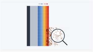
Corrosion is one of the most common causes of pressure vessel degradation. It occurs when the vessel material reacts with its environment, causing loss of thickness, pitting, cracking, or local weakening.
General corrosion reduces wall thickness over a broad area. Localised corrosion, such as pitting or crevice corrosion, can be more dangerous because it creates small, deep defects that concentrate stress. Corrosion under insulation is especially problematic because external damage can remain hidden until significant wall loss has occurred.
Internal corrosion may result from process fluids, water accumulation, acids, chlorides, oxygen, microbiological activity, or cleaning chemicals. External corrosion may result from weather exposure, damaged coatings, insulation moisture, marine environments, or poor drainage.
Prevention requires correct material selection, coatings, linings, corrosion allowance, cathodic protection where appropriate, process chemistry control, drainage, insulation management, and periodic thickness measurement.
Fatigue Failure
Fatigue failure occurs when a vessel or component experiences repeated stress cycles. The stress range may be below the material’s static strength, but repeated loading can initiate and grow cracks over time.
Pressure vessels may experience fatigue due to pressure cycling, start-up and shutdown cycles, thermal cycling, vibration, liquid sloshing, flow-induced vibration, rotating equipment loads, or pipe loads transmitted to nozzles.
Fatigue cracks often initiate at stress concentration points such as weld toes, nozzle openings, sharp transitions, attachment welds, supports, and areas with surface defects. Once a fatigue crack starts, it can grow gradually and may not be visible until it becomes significant.
Fatigue prevention requires identifying cyclic loads, reducing stress concentration, improving weld quality, avoiding resonance, controlling vibration, monitoring cycles, and using fatigue analysis during design or reassessment.
Stress Corrosion Cracking
Stress corrosion cracking, often called SCC, occurs when tensile stress, susceptible material, and a specific corrosive environment act together. Unlike general corrosion, SCC can create cracks with limited visible wall loss, making it difficult to detect without targeted inspection.
Stainless steels in chloride environments are a common example. Carbon steels, high-strength steels, and other alloys may also suffer SCC depending on service conditions.
SCC is dangerous because cracks can grow while the vessel appears externally acceptable. The failure may be brittle and sudden, especially when cracks reach a critical size.
Prevention involves selecting materials compatible with the environment, controlling contaminants, reducing tensile stress, applying stress relief where appropriate, avoiding stagnant areas, controlling temperature, and using suitable inspection methods such as ultrasonic testing, dye penetrant testing, magnetic particle testing, or advanced NDE techniques depending on the material and crack location.
Hydrogen Embrittlement
Hydrogen embrittlement occurs when hydrogen enters the metal and reduces ductility and toughness. This can make the material more vulnerable to cracking, particularly in high-strength steels or stressed weld regions.
Hydrogen may come from wet hydrogen sulphide service, acid cleaning, electrochemical reactions, corrosion processes, welding consumables, or certain process environments. Hydrogen damage can appear as cracking, blistering, loss of ductility, or delayed failure.
The risk is higher when susceptible material, tensile stress, and hydrogen exposure are present together. Weld heat-affected zones and high-hardness areas are common concern points.
Prevention includes proper material selection, hardness control, welding procedure control, preheating where required, post-weld heat treatment where applicable, avoiding hydrogen-producing environments, controlling corrosion, and using compatible cleaning and maintenance procedures.
Thermal Fatigue
Thermal fatigue occurs when repeated temperature changes create cyclic expansion and contraction. If parts of the vessel heat or cool at different rates, thermal gradients can create local stresses. Over time, these stresses can initiate cracks.
Thermal fatigue is common in vessels exposed to rapid start-up and shutdown, steam injection, quenching, hot and cold fluid mixing, batch processing, or cyclic heating. Nozzles, internal attachments, welds, and regions near inlet streams are often vulnerable.
Thermal fatigue may be difficult to predict if actual operating cycles differ from the original design basis. A vessel designed for steady operation may develop cracks if later used in frequent batch cycles.
Prevention requires understanding temperature profiles, controlling ramp rates, avoiding sudden thermal shock, improving mixing design, reducing local gradients, using suitable materials, and including thermal stress analysis where necessary.
Overpressure Failure
Overpressure failure occurs when internal pressure exceeds the vessel’s safe limit. This may result from blocked outlets, fire exposure, runaway reactions, control system failure, valve misoperation, thermal expansion of trapped liquid, pressure relief device failure, or incorrect operating procedures.
Overpressure can cause plastic deformation, leakage, rupture, or catastrophic burst. Even if a vessel does not fail immediately, overpressure events can permanently damage the vessel, reduce fatigue life, or compromise welds and attachments.
Prevention requires properly designed and maintained pressure relief systems, reliable instrumentation, pressure alarms, interlocks, safe operating procedures, operator training, and regular testing of safety valves and control systems.
Early Warning Signs of Pressure Vessel Failure
Pressure vessel failure often gives warning signs before a major incident occurs. Recognising these indicators early is essential for preventing escalation.
Leaks and Seepage
Leaks are one of the clearest warning signs of loss of containment. Even a small leak should not be ignored, especially near welds, nozzles, flanges, threaded connections, inspection openings, or repaired areas.
Seepage may indicate gasket failure, corrosion penetration, cracking, loose connections, or local distortion. Staining, moisture trails, crystallised deposits, chemical residue, or unusual odours can also indicate leakage.
Temporary sealing should never replace engineering assessment. The cause of the leak must be identified before the vessel is returned to reliable service.
Visible Cracks
Visible cracks are serious warning signs. They may appear on welds, heat-affected zones, nozzle connections, support attachments, shell surfaces, heads, or areas affected by vibration or thermal cycling.
Cracks may be straight, branched, curved, or associated with corrosion. Some cracks are visible only after surface cleaning or NDE. Any confirmed crack should be assessed for depth, length, location, growth potential, and remaining life.
Crack evaluation should consider whether the mechanism is fatigue, SCC, hydrogen damage, thermal fatigue, overload, or fabrication defect.
Excessive Vibration
Excessive vibration can accelerate fatigue damage in pressure vessels, nozzles, attachments, piping connections, supports, and instrumentation. Vibration may be caused by pumps, compressors, flow turbulence, vortex shedding, pressure pulsation, loose supports, poor alignment, or resonance.
Vibration is not always a direct vessel problem. It may originate from connected equipment but still transfer damaging cyclic loads into the vessel. Nozzle welds and small-bore connections are especially sensitive.
Engineers should investigate vibration using site measurements, operating data, modal analysis, and fatigue assessment when needed.
Corrosion Indicators
Corrosion indicators include rust, coating breakdown, blistering, insulation staining, wet insulation, wall thinning, pitting, scale, deposits, bulging, surface roughness, and local metal loss.
Internal corrosion may be suggested by process contamination, abnormal fluid chemistry, increased iron content, blocked drains, sediment, or recurring leaks. External corrosion may be hidden beneath insulation, supports, saddles, or inaccessible surfaces.
Corrosion should be mapped and trended over time. A single measurement is useful, but repeated measurements reveal the corrosion rate and remaining life.
How Engineers Investigate Pressure Vessel Failures
When a pressure vessel failure occurs, engineers must investigate systematically. The objective is not only to repair the damage but to understand the mechanism and prevent recurrence.
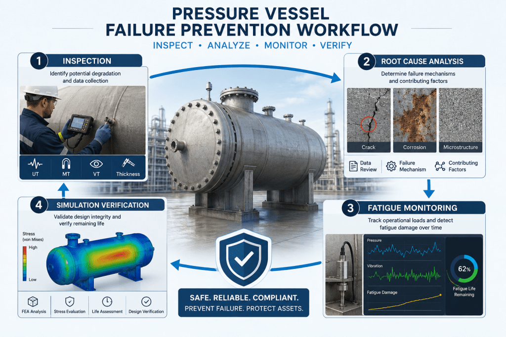
Inspection and Data Collection
The investigation begins with evidence. Engineers collect design drawings, material certificates, fabrication records, welding procedures, inspection reports, operating logs, pressure and temperature history, maintenance records, repair history, relief valve records, process chemistry data, and photographs.
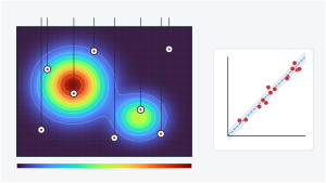
The failed area is inspected visually and with appropriate NDE methods. Thickness measurements, crack sizing, hardness testing, metallography, chemical analysis, fracture surface examination, and dimensional checks may be required depending on the case.
It is important to preserve evidence before cleaning, cutting, welding, or replacing parts. Valuable information can be lost if the failed area is disturbed too early.
Failure Mechanism Identification
After collecting data, engineers identify the physical mechanism of failure. This step answers the question: how did the vessel fail?
Possible mechanisms include corrosion thinning, pitting, fatigue cracking, stress corrosion cracking, hydrogen damage, thermal fatigue, brittle fracture, ductile overload, creep, buckling, erosion, or weld defect growth.
The mechanism must match the evidence. For example, a fatigue crack typically has features showing progressive crack growth, while overload failure shows different deformation and fracture characteristics. Corrosion-related failures may show metal loss, deposits, or environmental evidence. SCC may show branched cracking associated with specific materials and environments.
Correct mechanism identification is essential because the wrong mechanism leads to the wrong corrective action.
Root Cause Analysis
Failure mechanism identification explains the physical failure. Root cause analysis explains why the conditions existed.
For example, the mechanism may be corrosion thinning, but the root cause may be poor process chemistry control, inadequate inspection access, damaged coating, incorrect material selection, or failure to update inspection intervals after process changes.
Similarly, the mechanism may be fatigue cracking at a nozzle weld, while the root cause may be unsupported piping, resonance, poor weld profile, excessive pressure cycling, or lack of fatigue assessment during design.
Effective root cause analysis considers technical, operational, maintenance, procedural, and organisational factors. The goal is to prevent the same failure from recurring in the same vessel or similar assets.
Verification Through Simulation
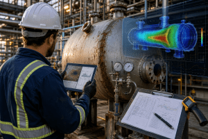
Simulation is often used to test failure hypotheses and verify corrective actions. Finite element analysis can identify stress concentration, deformation, thermal stress, nozzle loads, weld hotspot stresses, vibration modes, buckling risk, and fatigue damage.
For example, if cracks occur near a nozzle, simulation can determine whether pressure loads alone are sufficient to explain the cracking or whether piping loads, thermal gradients, or vibration must be included. If corrosion has reduced wall thickness, simulation can help evaluate whether the remaining section is still fit for service under current operating conditions.
Simulation is also valuable when assessing proposed repairs or design modifications. Engineers can compare the original design, damaged condition, and modified design before physical changes are made.
Prevention Strategies
Preventing pressure vessel failures requires a combination of design control, material control, fabrication quality, safe operation, inspection planning, and engineering analysis.
Proper Design Verification
Design verification ensures that the vessel is suitable for its intended service before fabrication or operation. This includes checking wall thickness, pressure rating, temperature limits, nozzle reinforcement, supports, fatigue exposure, corrosion allowance, external loads, relief systems, and compliance with applicable standards.
Design verification is especially important when a vessel operates under cyclic pressure, high temperature, corrosive service, external pressure, vacuum conditions, high nozzle loads, or unusual geometry.
For existing vessels, verification may be required after process changes, repairs, modifications, relocation, damage, or life extension assessments.
Material Selection
Correct material selection reduces the risk of corrosion, cracking, brittle fracture, hydrogen damage, and thermal degradation. Material decisions should consider process chemistry, pressure, temperature, weldability, toughness, corrosion resistance, availability, fabrication method, and inspection requirements.
Material selection should not be based only on strength. A stronger material is not always safer if it is more brittle, more sensitive to hydrogen, harder to weld, or less compatible with the environment.
Engineers should also consider coatings, linings, cladding, corrosion allowance, and environmental controls where base material alone is not sufficient.
Routine Inspection Programs
Routine inspection programs detect damage before failure. A strong program identifies the likely damage mechanisms and selects inspection methods accordingly.
Inspection may include visual inspection, ultrasonic thickness testing, radiography, magnetic particle testing, dye penetrant testing, acoustic emission, hardness testing, pressure testing, corrosion mapping, or advanced ultrasonic methods.
The inspection program should define what to inspect, where to inspect, how often to inspect, what method to use, what acceptance criteria apply, and what action is required if defects are found.
Inspection data should be trended over time. This allows engineers to estimate corrosion rates, crack growth, remaining life, and future inspection intervals.
Corrosion Management
Corrosion management is a long-term program, not a one-time inspection. It includes material selection, corrosion allowance, coatings, linings, insulation control, process chemistry monitoring, water control, inhibitor use, drainage, cathodic protection where applicable, and targeted inspection.
Corrosion risk should be reassessed when process conditions change. A small change in temperature, fluid composition, chloride level, pH, oxygen content, or water carryover can significantly change corrosion behaviour.
For insulated vessels, corrosion under insulation should be treated as a specific risk. Damaged insulation, poor weatherproofing, and trapped moisture can create severe external corrosion even when the vessel looks acceptable from a distance.
Fatigue Monitoring
Fatigue prevention requires understanding cyclic loading. Engineers should monitor pressure cycles, temperature cycles, vibration levels, start-up and shutdown frequency, process pulsation, and piping loads.
Where fatigue risk is high, fatigue analysis should be performed during design or reassessment. Critical areas should be inspected more frequently, especially welds, nozzles, attachments, supports, and small-bore connections.
Reducing fatigue risk may involve smoother operating procedures, improved supports, vibration mitigation, revised nozzle details, improved weld profiles, lower stress concentration, flexible piping design, or reduced pressure cycling.
Failure Prevention by Failure Type
Different failure types require different prevention strategies.
For corrosion damage, prevention focuses on compatible materials, coatings, linings, corrosion allowance, process chemistry control, insulation management, drainage, and thickness monitoring.
For fatigue failure, prevention focuses on reducing cyclic stress, controlling vibration, avoiding resonance, improving weld details, monitoring operating cycles, and performing fatigue analysis.
For stress corrosion cracking, prevention focuses on material compatibility, environment control, stress reduction, temperature control, contaminant control, and targeted crack inspection.
For hydrogen embrittlement, prevention focuses on material hardness control, hydrogen exposure control, welding procedure control, post-weld heat treatment where required, and environmental management.
For thermal fatigue, prevention focuses on controlled heating and cooling, avoiding rapid temperature changes, reducing thermal gradients, improving mixing, and performing thermal stress analysis.
For overpressure failure, prevention focuses on pressure relief design, relief valve testing, instrumentation, alarms, interlocks, operator training, and safe operating procedures.
The Role of Engineering Simulation in Failure Prevention
Engineering simulation plays a major role in modern pressure vessel integrity. It allows engineers to evaluate risk before physical failure occurs and to test corrective actions before expensive modifications are made.
Finite element analysis can show stress distribution, deformation, nozzle stresses, weld hotspot stresses, buckling behaviour, vibration modes, fatigue life, thermal gradients, and crack driving forces. Computational fluid dynamics can support investigations involving flow distribution, thermal mixing, erosion, fluid-induced vibration, and local hot or cold spots.
Simulation is most powerful when combined with real inspection data and operating measurements. Wall thickness readings, crack dimensions, vibration measurements, strain gauge data, pressure history, and temperature records can be used to create realistic models. This improves the accuracy of remaining life assessment and repair decisions.
For failure investigations, simulation helps answer questions such as:
Could the vessel have failed under normal pressure alone?
Did corrosion reduce the safety margin below an acceptable level?
Were nozzle loads higher than expected?
Did thermal gradients create local cracking?
Was vibration sufficient to initiate fatigue damage?
Will the proposed repair reduce the risk of recurrence?
For prevention, simulation helps engineers optimise design, verify compliance, improve inspection planning, and extend service life safely.
Conclusion
Pressure vessel failures are serious because they involve stored energy, hazardous materials, regulatory obligations, and operational continuity. Most failures are not caused by one isolated issue. They usually result from a combination of design assumptions, material behaviour, fabrication quality, operating conditions, inspection gaps, and maintenance decisions.
The most common pressure vessel failure mechanisms include corrosion damage, fatigue failure, stress corrosion cracking, hydrogen embrittlement, thermal fatigue, and overpressure. Each mechanism has different warning signs and requires a different prevention strategy.
Effective prevention begins with proper design verification and continues through material selection, welding quality control, safe operation, routine inspection, corrosion management, fatigue monitoring, and root cause analysis. When failures or warning signs occur, engineers must investigate the physical mechanism and the underlying root cause, not just repair the visible damage.
Engineering simulation strengthens this process by helping teams understand stress, temperature, vibration, crack growth, corrosion effects, and remaining life. When combined with inspection data and practical engineering judgement, simulation becomes a powerful tool for preventing pressure vessel failures before they become costly or dangerous incidents.
For industrial facilities, the goal should not only be compliance. The goal should be reliable, safe, and long-lasting pressure equipment supported by evidence-based engineering decisions.