Engineering simulation allows engineers to evaluate designs before manufacturing, installation, or construction begins.
However, not every simulation method solves the same problem.
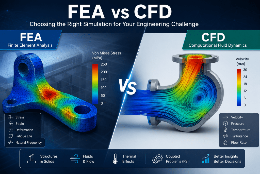
Two of the most widely used methods are Finite Element Analysis and Computational Fluid Dynamics. These methods are commonly known as FEA and CFD.
FEA usually evaluates the behaviour of solid structures. It predicts stress, deformation, vibration, fatigue, buckling, and other structural responses.
CFD focuses on fluids. It predicts how liquids and gases move, transfer heat, create pressure, and interact with surrounding surfaces.
The difference may sound simple. Yet many industrial problems contain both structural and fluid behaviour.
For example, fluid pressure can deform a pipe. Airflow can cool an electronic enclosure. Hot gas can heat a steel duct and create thermal stress.
Therefore, choosing between FEA and CFD requires more than identifying whether a system contains a solid or a fluid.
Engineers must define the physical problem, required outputs, operating conditions, and level of interaction between different domains.
This FEA vs CFD guide explains how both methods work. It also compares their inputs, outputs, applications, and computational requirements.
Most importantly, it explains when engineers should use FEA, CFD, or a coupled simulation approach.
What Is FEA?
Finite Element Analysis is a numerical simulation method used to predict how structures and solid materials respond to loads and operating conditions.
Engineers use FEA to calculate quantities such as:
- Stress
- Strain
- Deformation
- Displacement
- Vibration
- Natural frequency
- Fatigue life
- Temperature
- Heat conduction
- Contact pressure
- Buckling capacity
The method converts a complex structure into many smaller regions called finite elements.
Each element follows mathematical equations that describe its behaviour. The solver then combines the results from all elements.
This process produces an approximate solution for the complete structure.
FEA can represent simple parts, such as brackets and beams. It can also analyse complex systems, including pressure vessels, mining equipment, bridges, machinery, pipelines, and industrial structures.
The method is valuable because many real components cannot be assessed accurately with basic hand calculations alone.
A component may contain irregular geometry, changing thickness, several materials, welded connections, contact surfaces, or nonlinear behaviour.
FEA helps engineers understand how these details influence performance.
However, an FEA model is not automatically accurate. Its reliability depends on the geometry, mesh, material properties, loads, restraints, assumptions, and validation process.
How FEA Works
A typical FEA project follows several connected stages.
Each stage affects the quality of the final result.
1. Defining the Engineering Problem
The first step is to identify the question that the analysis must answer.
For example:
- Will the structure support the design load?
- Where will the highest stress occur?
- Will the component deform excessively?
- Could vibration cause resonance?
- What is the expected fatigue life?
- Will the structure buckle?
- How will thermal expansion affect the assembly?
A clear question helps engineers choose the correct type of analysis.
A static structural model cannot answer every engineering question. Dynamic, thermal, nonlinear, fatigue, or buckling analysis may also be required.
2. Preparing the Geometry
Engineers create or import a digital model of the component.
The original CAD model may include small details that do not affect structural performance. These details can increase model size without improving accuracy.
Therefore, engineers often simplify the geometry.
They may remove:
- Small cosmetic features
- Tiny holes
- Logos and markings
- Unimportant fillets
- Minor manufacturing details
- Components that do not affect the load path
However, important stress concentrations must remain.
Removing a critical weld detail, hole, notch, or thickness transition can hide the real peak stress.
3. Creating the Finite Element Mesh
The mesh divides the geometry into smaller elements.
A fine mesh can capture local stress changes more accurately. However, it also increases solution time and memory requirements.
A coarse mesh solves faster. Yet it may miss important stress concentrations.
Engineers normally refine the mesh near:
- Holes
- Welds
- Sharp corners
- Contact regions
- Load application points
- Thickness transitions
- Crack tips
- Geometric discontinuities
They may use a coarser mesh in areas with smooth stress variation.
Mesh convergence studies help confirm whether further refinement changes the result significantly.
4. Defining Material Properties
The FEA model requires material data.
For a basic linear elastic analysis, engineers usually define:
- Elastic modulus
- Poisson’s ratio
- Density
- Yield strength
- Thermal expansion coefficient
- Thermal conductivity
More advanced simulations may require additional data.
Examples include plastic stress-strain curves, creep properties, fatigue curves, damage models, composite properties, or temperature-dependent behaviour.
Using incorrect material data can make a detailed model unreliable.
5. Applying Loads and Boundary Conditions
Loads represent the forces and operating conditions acting on the structure.
Common loads include:
- Weight
- Pressure
- Mechanical force
- Torque
- Acceleration
- Temperature
- Wind
- Seismic loading
- Impact
- Vibration
- Thermal expansion
- Contact force
Boundary conditions represent how the structure connects to its surroundings.
They may describe fixed supports, sliding supports, bolts, bearings, welds, contact surfaces, or symmetry conditions.
Boundary conditions are among the most important parts of an FEA model.
An unrealistic fixed restraint can create false stress. In contrast, insufficient restraint can allow unrealistic movement.
Therefore, engineers must represent the actual load path.
6. Solving the Equations
The solver calculates the response of every element.
The solution process depends on the type of analysis.
A linear static model may solve quickly. A nonlinear model can require many load increments and iterations.
Nonlinearity may result from:
- Material yielding
- Large deformation
- Contact changes
- Friction
- Buckling
- Damage
- Changing stiffness
Dynamic models may also calculate behaviour over time or across a frequency range.
7. Reviewing and Validating the Results
The colourful contour plot is not the final engineering conclusion.
Engineers must review whether the results make physical sense.
They should check:
- Reaction force balance
- Deformed shape
- Stress distribution
- Mesh sensitivity
- Load path
- Boundary effects
- Energy balance
- Contact behaviour
- Comparison with hand calculations
- Comparison with measurements or tests
The final report should explain assumptions, limitations, acceptance criteria, and recommended actions.
Common FEA Applications
FEA supports many engineering disciplines.
Structural Stress Analysis
Structural analysis predicts stress and deformation under mechanical loads.
Engineers use it for frames, platforms, pressure equipment, supports, lifting devices, tanks, machinery, and infrastructure.
Nonlinear Analysis
Nonlinear FEA evaluates behaviour that changes with load.
It can represent material yielding, large displacement, changing contact, friction, and complex load transfer.
Dynamic and Vibration Analysis
Dynamic FEA predicts how structures respond to changing loads.
Common studies include:
- Natural frequency analysis
- Modal analysis
- Harmonic response
- Random vibration
- Seismic response
- Impact analysis
- Transient dynamics
Fatigue Analysis
Fatigue analysis estimates damage caused by repeated loading.
It helps engineers identify fatigue-critical regions and predict service life.
Buckling Analysis
Buckling analysis evaluates instability in columns, shells, vessels, panels, and slender structures.
It may include ideal elastic buckling or nonlinear collapse analysis.
Thermal Stress Analysis
Thermal FEA predicts stress caused by temperature changes.
It is useful for pressure vessels, furnaces, piping, engines, refractory systems, and equipment exposed to start-up and shutdown cycles.
Fracture Mechanics
Fracture mechanics models evaluate components that contain cracks or crack-like defects.
The analysis may calculate stress intensity factors, crack-driving forces, or critical crack size.
What Is CFD?
Computational Fluid Dynamics is a numerical method used to predict the behaviour of liquids and gases.
CFD calculates how a fluid moves through or around a system.
It can also evaluate pressure, temperature, turbulence, heat transfer, species transport, combustion, and multiphase behaviour.
Common CFD outputs include:
- Fluid velocity
- Static pressure
- Dynamic pressure
- Pressure loss
- Temperature
- Turbulence intensity
- Flow direction
- Mass flow rate
- Heat transfer rate
- Species concentration
- Particle trajectories
- Residence time
CFD is based on equations that describe conservation of mass, momentum, and energy.
These equations are difficult to solve directly for complex industrial systems.
Therefore, CFD divides the fluid region into many smaller control volumes or cells.
The solver calculates the flow behaviour in each cell. It then combines the results to represent the complete fluid domain.
CFD allows engineers to see flow features that may be difficult to measure physically.
Examples include recirculation zones, stagnant regions, high-velocity jets, pressure losses, thermal hotspots, and uneven flow distribution.
How CFD Works
A CFD project also follows a structured workflow.
However, the inputs and modelling decisions differ from structural FEA.
1. Defining the Fluid Domain
CFD usually models the space occupied by the fluid.
For internal flow, this may include the space inside:
- Pipes
- Ducts
- Valves
- Pumps
- Tanks
- Ventilation systems
- Heat exchangers
- Process equipment
For external flow, the fluid domain surrounds the object.
Examples include airflow around buildings, vehicles, stacks, structures, or equipment.
The engineer must create a fluid volume with suitable inlet, outlet, wall, and far-field boundaries.
2. Generating the CFD Mesh
The fluid domain is divided into computational cells.
The mesh must capture important flow features.
Engineers often refine the mesh near:
- Walls
- Inlets and outlets
- Sharp bends
- Valves
- Nozzles
- Narrow passages
- Heat transfer surfaces
- Separation zones
- Rotating components
- High-gradient regions
Near-wall mesh quality is especially important for turbulent flow and heat transfer.
Boundary-layer inflation cells help represent rapid velocity changes close to solid surfaces.
3. Defining Fluid Properties
The model requires suitable fluid properties.
These may include:
- Density
- Dynamic viscosity
- Specific heat
- Thermal conductivity
- Compressibility
- Vapour pressure
- Molecular weight
- Diffusion coefficients
Some properties change with pressure or temperature.
For high-temperature, compressible, or multiphase systems, constant properties may not be suitable.
4. Selecting the Physical Models
The engineer chooses the equations and models needed for the problem.
Common choices include:
- Laminar or turbulent flow
- Steady-state or transient flow
- Compressible or incompressible flow
- Single-phase or multiphase flow
- Heat transfer
- Radiation
- Combustion
- Species transport
- Particle tracking
- Rotating machinery
- Porous media
The model should include enough physics to answer the engineering question.
However, adding unnecessary complexity can increase solution time and make convergence more difficult.
5. Applying CFD Boundary Conditions
CFD boundary conditions describe how fluid enters, exits, and interacts with surfaces.
Common inputs include:
- Inlet velocity
- Mass flow rate
- Volumetric flow rate
- Inlet pressure
- Outlet pressure
- Fluid temperature
- Heat flux
- Wall temperature
- Surface roughness
- Fan performance
- Pump performance
- Rotational speed
Poor boundary conditions can produce misleading results.
For example, an unrealistic outlet location may affect the upstream flow pattern.
Therefore, engineers should place model boundaries far enough from the region of interest.
6. Solving the Flow Equations
The CFD solver repeatedly updates pressure, velocity, temperature, and other variables.
This iterative process continues until the solution reaches an acceptable level of convergence.
Engineers monitor:
- Equation residuals
- Mass balance
- Energy balance
- Pressure drop
- Flow rate
- Temperature
- Forces
- Other engineering quantities
Low residuals alone do not prove that the solution is correct.
The monitored physical results must also become stable.
7. Interpreting the CFD Results
CFD results may include contours, streamlines, vectors, graphs, and animations.
These visualisations help engineers locate:
- Flow separation
- Recirculation
- Dead zones
- High-pressure regions
- Excessive velocity
- Uneven distribution
- Thermal hotspots
- Poor ventilation
- High turbulence
- Particle accumulation
The final interpretation should connect the simulation results with performance, safety, and design requirements.
Common CFD Applications
CFD is used whenever fluid behaviour affects system performance.
Pipe and Duct Flow
CFD calculates pressure drop, velocity distribution, flow separation, and energy loss.
It also helps engineers evaluate fittings, bends, valves, manifolds, and branches.
Ventilation and HVAC
CFD predicts airflow, temperature, contaminant movement, and thermal comfort.
Applications include buildings, tunnels, workshops, mines, warehouses, laboratories, and industrial plants.
Heat Exchangers
CFD evaluates fluid distribution and heat transfer.
It can identify bypass flow, stagnant zones, poor thermal performance, and excessive pressure loss.
Aerodynamics
External-flow CFD predicts drag, lift, wake behaviour, and wind pressure.
It supports vehicles, buildings, structures, fans, and rotating equipment.
Pumps, Fans, and Turbomachinery
CFD evaluates rotating-flow performance.
Engineers can predict efficiency, pressure rise, cavitation risk, and flow instability.
Combustion and Process Engineering
CFD can simulate fuel mixing, chemical reaction, emissions, heat release, and combustion temperature.
Multiphase Flow
Multiphase CFD evaluates systems containing more than one phase.
Examples include gas-liquid flow, slurry transport, sedimentation, boiling, spray, and particle-laden airflow.
FEA vs CFD: Key Differences
FEA and CFD are both numerical simulation methods.
They also share several workflow stages.
Both require geometry preparation, meshing, material or fluid properties, boundary conditions, solving, post-processing, and validation.
However, they solve different physical problems.
FEA primarily evaluates solids and structures.
CFD primarily evaluates fluids and transport processes.
The correct choice depends on the engineering question.
Physics Being Solved
The main difference between FEA and CFD is the governing physics.
FEA often solves equations related to structural equilibrium.
These equations describe how a solid reacts to force, pressure, acceleration, temperature, and restraint.
The main unknowns may include displacement, stress, strain, or temperature.
CFD solves equations related to fluid conservation.
These equations describe conservation of:
- Mass
- Momentum
- Energy
- Chemical species
The main unknowns may include pressure, velocity, temperature, and concentration.
However, the boundaries are not absolute.
FEA can solve heat conduction through solids. CFD can calculate pressure forces acting on walls.
The methods may also exchange results during a coupled simulation.
Input Data Requirements
FEA requires accurate information about the solid structure.
Typical FEA inputs include:
- Geometry and thickness
- Material stiffness
- Yield strength
- Density
- Loads
- Supports
- Contact definitions
- Temperature
- Fatigue data
- Joint properties
CFD requires accurate information about the fluid domain.
Typical CFD inputs include:
- Fluid geometry
- Fluid density
- Viscosity
- Flow rate
- Pressure
- Temperature
- Turbulence conditions
- Surface roughness
- Heat sources
- Fan or pump performance
Both methods depend heavily on boundary conditions.
However, the nature of those boundary conditions is different.
FEA focuses on forces, constraints, and structural connections.
CFD focuses on flow, pressure, temperature, and wall interaction.
Output Results
FEA results describe the behaviour of the solid structure.
Common outputs include:
- Stress
- Strain
- Displacement
- Reaction force
- Contact pressure
- Fatigue life
- Buckling factor
- Natural frequency
- Thermal stress
CFD results describe the behaviour of the fluid.
Common outputs include:
- Velocity
- Pressure
- Temperature
- Pressure drop
- Turbulence
- Heat transfer coefficient
- Flow rate
- Species concentration
- Particle path
- Residence time
The outputs may connect.
For example, CFD pressure can become a load in FEA.
Similarly, FEA deformation can change the shape of the CFD fluid domain.
Computational Requirements
FEA and CFD can both require significant computing resources.
However, CFD models often contain more cells and require more iterative calculations.
A steady, incompressible CFD model may still require millions of cells.
Transient turbulence, combustion, multiphase flow, or rotating machinery can increase computational demand substantially.
FEA requirements depend on the analysis type.
A simple linear static model may solve quickly. In contrast, nonlinear contact, impact, fracture, or transient dynamic models may require extensive computing time.
The following factors increase computational demand in both methods:
- Fine mesh
- Complex geometry
- Nonlinear behaviour
- Transient simulation
- Multiple materials or phases
- Large result files
- Coupled physics
- High accuracy requirements
Engineers should choose model complexity based on the project objective.
The most complex model is not always the most useful model.
When Should You Use FEA?
Use FEA when the main concern relates to the behaviour of a solid component or structure.
The analysis should answer a structural, mechanical, thermal-stress, or durability question.
Structural Integrity Assessment
FEA is suitable when engineers must determine whether a structure can support its loads safely.
It can identify:
- High-stress regions
- Excessive deformation
- Weak load paths
- Local yielding
- Contact problems
- Buckling risk
- Connection forces
Structural integrity assessment may apply to new designs or existing equipment.
For existing assets, engineers may include corrosion loss, damage, modifications, or measured geometry.
Fatigue Analysis
Use FEA when repeated loading may cause fatigue damage.
The structural model calculates the stress range at critical locations.
Engineers then combine the stress results with fatigue data and operating cycles.
Fatigue analysis is common for:
- Welded structures
- Rotating machinery
- Pressure equipment
- Mining equipment
- Cranes
- Bridges
- Vibrating systems
- Cyclic thermal equipment
Dynamic analysis may also be required when vibration contributes to fatigue.
Design Verification
FEA supports design verification when hand calculations cannot represent the geometry or loading accurately.
It can demonstrate whether the design meets:
- Strength requirements
- Deflection limits
- Stability requirements
- Fatigue criteria
- Thermal limits
- Code requirements
- Client specifications
However, the verification process must define clear acceptance criteria before reviewing the results.
When Should You Use CFD?
Use CFD when fluid motion, pressure, temperature, or transport behaviour controls performance.
The main question should concern how a liquid or gas moves through or around a system.
Fluid Flow Optimisation
CFD helps engineers improve flow distribution while reducing pressure loss.
It can compare design alternatives before fabrication.
For example, CFD can optimise:
- Pipe routing
- Duct geometry
- Manifolds
- Nozzles
- Valves
- Diffusers
- Mixing systems
- Pump inlets
- Fan systems
The results may reveal that a small geometry change improves performance significantly.
Heat Transfer Analysis
Use CFD when convection plays an important role in heat transfer.
CFD can calculate the interaction between fluid velocity and temperature.
Applications include:
- Heat exchangers
- Electronics cooling
- Furnaces
- Boilers
- Engine cooling
- Battery systems
- Industrial drying
- Thermal processing
If the main concern is heat conduction through a solid, thermal FEA may be sufficient.
However, CFD is usually required when airflow or liquid flow controls the heat transfer rate.
Ventilation and Exhaust Systems
CFD is especially useful for ventilation systems.
It can predict how effectively a system removes heat, dust, fumes, gases, or airborne contaminants.
Engineers can assess:
- Air distribution
- Extraction efficiency
- Short-circuiting
- Dead zones
- Thermal comfort
- Contaminant concentration
- Exhaust placement
- Fan performance
The results help improve both safety and energy efficiency.
Can FEA and CFD Be Used Together?
Yes. Many engineering systems require both FEA and CFD.
A fluid may create pressure or temperature loads on a structure.
The structure may then deform.
That deformation may also change the fluid flow.
A coupled simulation allows engineers to study these interactions.
The simplest approach is one-way coupling.
In a one-way simulation, CFD calculates the fluid loads first.
The pressure or temperature results are then transferred to the FEA model.
The structural deformation does not return to the CFD model.
One-way coupling is suitable when deformation has little effect on the flow.
Two-way coupling is more advanced.
The CFD model sends pressure and temperature loads to FEA. The FEA model calculates deformation.
The changed shape then returns to the CFD model.
This exchange continues during the simulation.
Two-way coupling is needed when structural deformation significantly changes the fluid behaviour.
Fluid-Structure Interaction
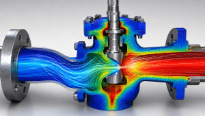
Fluid-Structure Interaction is commonly known as FSI.
FSI models the interaction between moving fluids and deformable structures.
Applications include:
- Flexible pipes
- Pressure vessels
- Valves
- Turbine blades
- Aircraft wings
- Cooling fans
- Offshore structures
- Blood vessels
- Membranes
- Heat exchanger tubes
- Chimneys and stacks
For example, airflow can cause a flexible panel to vibrate.
The vibration changes the airflow. The altered airflow then changes the force on the panel.
This feedback can produce instability, fatigue, or failure.
FSI can also include thermal effects.
Hot fluid may heat a structure. The structure expands and deforms. The deformation then changes the fluid passage.
Therefore, some projects require fluid, thermal, and structural simulations together.
Because FSI models are complex, engineers should confirm whether full two-way coupling is necessary.
In many cases, a one-way transfer provides sufficient accuracy at a lower computational cost.
FEA vs CFD Comparison Table
| Comparison Area | FEA | CFD |
|---|---|---|
| Full name | Finite Element Analysis | Computational Fluid Dynamics |
| Primary domain | Solids and structures | Liquids and gases |
| Main purpose | Predict structural and material response | Predict fluid flow and transport behaviour |
| Common physics | Stress, strain, deformation, vibration, fatigue and buckling | Velocity, pressure, turbulence, heat transfer and species transport |
| Typical geometry | Solid structural model | Internal or external fluid volume |
| Main material data | Elastic modulus, strength, density and fatigue properties | Density, viscosity, thermal properties and compressibility |
| Common boundary conditions | Force, pressure, support, contact and temperature | Velocity, flow rate, pressure, temperature and wall conditions |
| Common outputs | Stress, displacement, fatigue life and natural frequency | Velocity, pressure drop, temperature and turbulence |
| Common mesh focus | Stress concentrations, contact and geometric discontinuities | Boundary layers, flow separation and high-gradient regions |
| Typical applications | Structures, machinery, vessels, supports and mechanical components | Pipes, ducts, ventilation, pumps, fans and heat exchangers |
| Thermal capability | Conduction and thermal stress in solids | Convection, fluid temperature and conjugate heat transfer |
| Dynamic capability | Vibration, impact and structural transient response | Transient flow, vortex shedding and unsteady thermal behaviour |
| Coupled use | Receives pressure and temperature loads from CFD | Provides pressure and temperature loads to FEA |
| Typical computing demand | Low to very high, depending on nonlinearity and dynamics | Moderate to very high, especially for transient turbulent flow |
| Best choice when | Solid strength or deformation controls the design | Fluid behaviour controls the design |
Common Mistakes When Choosing Between FEA and CFD
Selecting the wrong method can waste time and produce irrelevant results.
Several mistakes occur frequently.
Choosing Software Before Defining the Problem
Engineers should define the physical question first.
Software should support the required analysis. It should not determine which question gets asked.
Assuming Every Thermal Problem Requires CFD
Not every heat transfer problem involves fluid flow.
If heat moves mainly through a solid, thermal FEA may provide the required result.
CFD becomes more important when convection, airflow, liquid flow, or fluid mixing controls the temperature.
Using FEA Pressure Loads Without Understanding the Flow
A uniform pressure may not represent a real fluid system.
Flow can create local pressure peaks, suction, pulsation, and uneven distribution.
CFD may be needed to calculate realistic pressure loads.
Ignoring Structural Response in a CFD Project
CFD may predict the fluid performance successfully.
However, the pressure or temperature may create unacceptable structural stress.
Therefore, the project may also require FEA.
Ignoring Fluid-Structure Interaction
One-way coupling is not always sufficient.
If deformation changes the flow path significantly, a two-way FSI model may be necessary.
Applying Unrealistic Boundary Conditions
Both FEA and CFD depend on realistic boundaries.
An incorrect support can distort FEA stress.
An incorrect inlet or outlet can distort CFD flow.
Engineers should base model inputs on drawings, measurements, operating data, or justified assumptions.
Using an Inadequate Mesh
A coarse mesh may miss critical behaviour.
In FEA, it may miss stress concentrations.
In CFD, it may miss boundary layers, separation, or jets.
Mesh sensitivity checks should form part of the analysis.
Adding Unnecessary Complexity
Complexity does not guarantee accuracy.
A highly detailed model with uncertain inputs may be less useful than a simpler model with reliable data.
Engineers should include only the physics needed to answer the project question.
Relying Only on Colour Contours
Colourful results can look convincing.
However, the contour range can change the appearance significantly.
Engineers should review numerical values, balances, convergence, trends, and acceptance limits.
Failing to Validate the Model
Simulation should be checked against independent information.
Validation may include:
- Hand calculations
- Code equations
- Published test data
- Site measurements
- Pressure readings
- Temperature readings
- Strain measurements
- Physical testing
- Previous operating data
Without validation, the model remains an unconfirmed prediction.
How to Choose Between FEA and CFD
Start with the main engineering question.
Use FEA when the question focuses on:
- Strength
- Stress
- Deformation
- Fatigue
- Vibration
- Buckling
- Structural temperature
- Thermal expansion
Use CFD when the question focuses on:
- Fluid velocity
- Pressure loss
- Airflow
- Liquid flow
- Turbulence
- Mixing
- Convection
- Ventilation
- Fluid temperature
Use both when fluid behaviour creates structural loads or structural movement changes the flow.
Examples include pressure-loaded vessels, flexible ducts, turbine blades, heat exchanger tubes, cooling systems, and offshore structures.
In some cases, the project can begin with a simplified simulation.
Engineers may use CFD to determine pressure loads. They can then transfer those loads to FEA.
If the deformation remains small, the one-way approach may be enough.
If the deformation changes the flow, the project can progress to two-way FSI.
This staged approach controls cost while maintaining engineering value.
The Importance of Engineering Judgement
FEA and CFD are powerful tools.
However, neither method replaces engineering judgement.
Software solves the equations defined by the user.
It does not automatically determine whether the assumptions reflect the real system.
Reliable simulation requires engineers to understand:
- Physical behaviour
- Operating conditions
- Material or fluid properties
- Numerical limitations
- Measurement uncertainty
- Applicable standards
- Failure mechanisms
- Validation methods
The final engineering decision should consider both simulation results and practical evidence.
A technically impressive model is not useful if it does not answer the project question.
How Avesta Consulting Supports FEA and CFD Projects
FEA and CFD projects require more than access to simulation software.
They require suitable modelling strategies, realistic inputs, verification checks, and clear engineering interpretation.
Avesta Consulting applies advanced simulation methods to structural, mechanical, fluid, and thermal engineering problems.
Depending on the project, the work may include:
- Linear and nonlinear FEA
- Static and dynamic structural analysis
- Vibration assessment
- Fatigue life analysis
- Thermal stress analysis
- Buckling analysis
- Internal and external CFD
- Turbulent flow modelling
- Heat transfer analysis
- Ventilation assessment
- Multiphase flow
- Conjugate heat transfer
- Fluid-Structure Interaction
- Design verification
- Performance optimisation
The correct simulation method depends on the problem.
Some projects require only structural FEA. Others require detailed CFD.
Complex systems may require both methods and a carefully managed transfer of results.
A clear analysis plan helps control modelling time and provides results that support practical decisions.
Frequently Asked Questions
Is FEA the same as CFD?
No.
FEA mainly predicts the behaviour of solids and structures. CFD mainly predicts the behaviour of liquids and gases.
However, both are numerical simulation methods.
Is CFD a type of FEA?
CFD and FEA use related numerical principles. However, they usually solve different governing equations and physical domains.
Some CFD solvers use finite volume methods, while others may use finite element methods.
In practical engineering, CFD and structural FEA are normally treated as separate analysis disciplines.
Can FEA analyse heat transfer?
Yes.
FEA can calculate steady-state or transient heat conduction through solids.
It can also calculate thermal expansion and thermal stress.
CFD is usually more suitable when moving fluids control the heat transfer.
Can CFD calculate structural stress?
CFD calculates fluid pressure and shear forces.
These loads can then be transferred to an FEA model to calculate structural stress and deformation.
CFD alone does not normally provide a complete structural integrity assessment.
Which method is more computationally demanding?
The answer depends on model complexity.
CFD often requires large meshes and many solver iterations.
However, nonlinear, transient, dynamic, or contact-based FEA can also require major computing resources.
What is the difference between FEA and FSI?
FEA evaluates structural behaviour.
FSI combines fluid and structural behaviour.
An FSI model usually connects CFD results with an FEA structural model.
Do all FEA and CFD projects require 3D models?
No.
Two-dimensional, axisymmetric, beam, shell, or simplified models may provide suitable results.
The model dimension should match the geometry, physics, and project objective.
Can simulation replace physical testing?
Simulation can reduce the amount of testing required.
However, testing and measurement remain important for validation.
The best approach often combines simulation with engineering calculations and physical evidence.
Conclusion
FEA and CFD solve different but closely connected engineering problems.
FEA focuses mainly on solids and structures. It predicts stress, deformation, vibration, fatigue, buckling, and thermal response.
CFD focuses mainly on liquids and gases. It predicts velocity, pressure, turbulence, temperature, mixing, and heat transfer.
The correct choice starts with the engineering question.
Use FEA when structural strength, deformation, durability, or vibration controls performance.
Use CFD when flow distribution, pressure loss, ventilation, cooling, or fluid behaviour controls performance.
Many industrial systems require both methods.
CFD can calculate fluid pressure and temperature. FEA can then calculate the resulting stress and deformation.
When structural movement changes the flow, engineers may require two-way Fluid-Structure Interaction.
Regardless of the method, reliable results depend on realistic geometry, properties, boundary conditions, meshing, validation, and engineering judgement.
A well-planned FEA or CFD study does more than produce visual results.
It identifies risks, improves performance, supports design verification, and helps engineering teams make evidence-based decisions.