A steel shell that has lost thickness to corrosion does not announce when it has become unsafe. It may look sound, pass a routine pressure or load check on paper, and still be close to local buckling, cracking at a repair weld or excessive deformation. For plant managers and asset owners, the practical question is simple: should this equipment stay in service, be repaired, or be replaced? A rigorous corroded steel shell assessment answers it with evidence instead of judgement alone. This article explains how wall thinning affects structural integrity, how an assessment is carried out, which methods and standards apply, and how repair options such as overplating should be evaluated.
How Corrosion and Wall Thinning Affect Structural Integrity
A steel shell carries load through its thickness. Internal pressure creates membrane (hoop and longitudinal) stress, and external loads such as self-weight, contents, wind, thermal expansion and supported equipment add compression, bending and shear. When corrosion or erosion removes metal, remaining wall thickness falls, and three things happen:
- Stress rises. For a given load, stress is inversely related to thickness. Even modest wall loss raises membrane stress across the whole thinned region, and localised thinning raises it further around the edges of the thinned area.
- Stability falls faster than strength. Thin-walled shells resist compression through their curvature and thickness, and their resistance to buckling depends strongly on the thickness-to-radius ratio. A shell can therefore lose a larger proportion of its buckling capacity than its simple tensile capacity, which is why local buckling can appear in a vessel that is still adequate for pressure.
- Sensitivity to imperfections grows. Out-of-roundness, weld distortion, dents and previous deformation reduce buckling capacity in thin shells, and thinning makes their effect more pronounced.
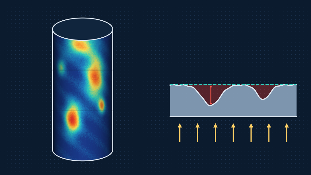
Corrosion rarely occurs evenly. General wall loss, pitting, grooving at welds and erosion in high-velocity or abrasive zones create an uneven thickness map with thin patches next to relatively sound plate. Those transitions produce stress concentrations and can trigger local deformation long before the average thickness looks critical.
The consequences range from bulging and buckled panels to cracking, leaks and, in the worst cases, loss of containment or structural collapse. For equipment with a design basis that has changed since it was built, formal design verification against the current condition and loads is the way to confirm that the shell still meets its required capacity.
How to Assess a Corroded Steel Shell
A sound assessment starts with understanding the equipment as it is now, not as it was designed. Four groups of information are needed.
- Remaining wall thickness. Ultrasonic thickness measurements, thickness grids or scans, and records of previous inspections show how much metal is left and where. A thickness history also allows a corrosion or erosion rate to be estimated, which is essential if the equipment is to run until the next shutdown or beyond.
- Geometry. Shell diameter, height, head and cone details, stiffeners, nozzles and openings, and any measured deformation or out-of-roundness all affect how the shell responds. Real, measured geometry is more useful than drawing dimensions when the shell has already deformed.
- Loading conditions. Internal or external pressure (including vacuum), temperature and thermal cycling, self-weight and contents, supported loads, wind or seismic loads, and any eccentric or localised loads all need to be defined for the governing operating and upset cases.
- Inspection and history data. Coating condition, corrosion mechanism, previous repairs, welds and weld details, fabrication records and operating history help explain why the damage occurred and whether it is likely to continue.
Why thickness measurements alone are not enough
Thickness readings tell you how much steel is left at the points where it was measured. They do not, by themselves, tell you whether the shell can carry its loads. Three issues explain the gap:
- Where the thin area is matters. A thin patch near a nozzle, a support or a weld sees different stresses than one in a quiet region of the shell.
- Shape and extent matter. A small deep pit and a large shallow thinned area behave differently, and a minimum reading on its own does not describe either of them.
- Loads interact with deformation. Once a shell has bulged or buckled locally, the load path changes. The result can be higher stress and lower buckling margin than a thickness-based calculation suggests.
For these reasons, a thickness comparison against a minimum required value is a useful screening step, but not an engineering conclusion where there is deformation, complex loading, localized thinning or high consequence of failure.
Which Engineering Methods and Standards Apply?
The role of FEA
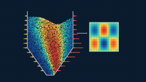
Finite element analysis (FEA) is used when simple formulas cannot capture the geometry, the thinned areas or the combination of loads. A model that includes the measured or corroded thickness distribution can predict:
- Stress and deformation under pressure, weight, thermal and other loads.
- Buckling load factors, showing how close the shell is to local or global instability, and the effect of imperfections such as out-of-roundness.
- The effect of a proposed repair or modification before it is built.
FEA results are only as reliable as their inputs. The thickness data, load cases, boundary conditions and material properties need to be documented, and the results should be checked against the governing acceptance criteria.
Standards
The applicable standard depends on what the equipment is and where it is installed, so it should be selected for each case rather than assumed. Examples include:
- AS 1210 for pressure vessels in Australia.
- AS 4100 for steel structures, applied where the shell or bin behaves as a structural item and the design basis is structural steelwork.
- ASME Boiler and Pressure Vessel Code requirements where the vessel was built to ASME.
A standard sets the acceptance criteria, but it may not directly address a corroded or deformed component. That is where fitness-for-service thinking comes in.
Fitness-for-service (FFS)
Fitness-for-service (FFS) assessment evaluates whether equipment with known damage, such as corrosion, wall thinning, dents or cracks, can continue to operate safely under defined conditions, and for how long. Recognized FFS frameworks, such as API 579-1/ASME FFS-1, define levels of assessment from simple screening to detailed analysis. An FFS-type assessment typically considers the damage mechanism, the remaining thickness profile, the loads, the consequences of failure and the inspection or monitoring needed to keep operating.
Where cracking or crack-like flaws are present, or are suspected near welds, fracture mechanics analysis can quantify whether a flaw is likely to grow. Where the cause of damage is unclear, root cause failure analysis identifies what drove the deterioration so that a repair does not simply repeat the problem. Our guides to common pressure vessel failures and pressure vessel design verification explain how these steps fit into a wider integrity process.
Repair, Reinforcement or Replacement?
Once the condition and capacity are understood, the choice is usually between four paths.
- Continue operating with limits. If the assessment shows adequate margin, the equipment may continue running with defined limits on pressure, load or operating level, plus a monitoring and re-inspection plan.
- Overplanting (reinforcement). A plate is fitted over the thinned region and welded to the shell to restore local capacity. It can be a practical option for localized damage when shutdown time is limited.
- Replace the damaged section. The corroded or deformed portion is cut out and replaced with new plate, which restores the original condition but needs welding procedures, inspection and, in some cases, heat treatment.
- Replace the equipment. When damage is widespread, the corrosion mechanism cannot be controlled, or the remaining life does not justify repair, replacement may be the more reliable and economical decision.
The repair must be assessed too
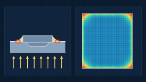
A repair is a structural change, and it can introduce new problems if it is not evaluated. For an over plate or an insert, the assessment should consider:
- Stress concentrations at plate edges, weld terminations and the transition between old and new material, where load has to flow into the repair.
- Weld fatigue, especially where the equipment sees cyclic pressure, thermal cycling or vibration, since fillet welds around the edge of a patch can be fatigue-sensitive details.
- Thermal effects, because a plate that is heated or cooled differently from the shell can create differential expansion and additional stress.
- Ongoing corrosion, such as corrosion beneath or behind a patch that cannot be inspected, and whether the underlying cause has been addressed.
- Local buckling and deformation of both the repair and the surrounding shell under the governing loads.
Checking these effects with analysis before fabrication reduces the risk of a repair that works on paper but fails early in service.
Case Study: Stove Pressure Vessel DCD Over-Plating Repair Analysis
Avesta assessed a proposed overplanting repair for a stove pressure vessel at BlueScope Steel. The vessel had experienced corrosion, reduced wall thickness and shell deformation, so the question was not only how much capacity the corroded shell had, but whether the proposed repair would perform safely in service.
The engineering assessment used thermal-structural FEA to evaluate the shell and the proposed over plating under the operating thermal and mechanical conditions, and weld fatigue assessment to evaluate the repair welds, which are often the critical details in an over plating repair. Combining these analyses allowed the repair to be assessed for stresses and fatigue life before it was committed to, rather than judged by thickness alone.
Read the full details on the Stove Pressure Vessel DCD Over Plating Repair Analysis project page.
Case Study: PCI Bin Design Modification
Corrosion and erosion are not always the only contributors to a buckling problem, and a good assessment keeps them in context. On the PCI coal bin at BlueScope Steel’s Port Kembla operations, the bin had experienced localized buckling in the wall quadrant next to the trouser leg discharge.
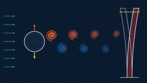
Avesta’s assessment determined the most likely cause of the buckling deformation by considering wall erosion together with eccentric roof bulk material loading and out-of-roundness. The structural FEA considered the corroded and eroded wall thickness and the proposed design modifications, and established the minimum buckling load factor, deflections and stresses. The results defined limiting roof loads and wall thickness to enable continued operation of the bin, including post-buckling conditions with and without the wall modifications.
The lesson for corroded shells is that thickness loss is one input among several. Read the full PCI Bin Design Modification project to see how corrosion, erosion, eccentric loading and out-of-roundness were assessed together.
What Information Is Needed for an Engineering Assessment?
The more complete the data package, the faster and more defensible the assessment. Typical information includes:
- Drawings and design data: general arrangement and detail drawings, design code, design pressure and temperature, and original design thickness and corrosion allowance.
- Measured thicknesses: the latest thickness survey with locations, previous surveys for corrosion rate estimation, and a map of the thinnest areas.
- Deformation data: photographs, dimensional surveys, out-of-roundness or bulge measurements and any scans.
- Material properties: material grade, certificates or test results and weld details.
- Loading conditions and operating data: pressure, temperature, thermal cycles, contents and fill levels, external loads, and upset or abnormal cases.
- Repair and inspection history: earlier repairs, modifications, inspection reports, failure reports and the corrosion mechanism if known.
- Decision context: target remaining life, available shutdown window and the consequences of failure.
If some of this is missing, an assessment can often still proceed with documented assumptions and sensitivity checks. The industries where this is most often needed include steel, high temperature pressure vessels, mining and resources and minerals processing.
Frequently Asked Questions
How does wall thinning affect structural integrity?
Wall thinning reduces the thickness available to carry load, which raises stress and lowers resistance to buckling. Because buckling capacity depends strongly on thickness relative to the shell radius, a thinned region can become unstable even when the shell is still strong enough for pressure alone. Localized thinning also creates stress concentrations and can lead to bulging, deformation or cracking.
Can FEA assess a corroded pressure vessel?
Yes. FEA can include the measured or corroded thickness distribution, the real geometry and the combination of pressure, thermal and mechanical loads to predict stress, deformation and buckling margin. It is typically used alongside inspection data and a fitness-for-service or code-based framework, so that the results are compared against defined acceptance criteria.
When is over plating a suitable repair option?
Over plating can be suitable when damage is localized, the underlying corrosion mechanism is understood and controlled, and the repair has been shown by analysis to carry the loads without creating unacceptable stress concentrations or weld fatigue risk. It is less suitable where damage is widespread, where cracking is present, or where the covered area cannot be inspected and corrosion may continue unseen.
Should a corroded steel shell be repaired or replaced?
There is no single answer. The decision depends on the remaining thickness and its trend, the structural margin shown by assessment, the damage mechanism, the consequences of failure, the cost and time available for repair, and the remaining life needed. An engineering assessment compares these factors so the owner can choose between continued operation with limits, repair, section replacement or full replacement.
Talk to Avesta About Corroded, Thinned or Buckled Equipment
If you manage a vessel, bin, stack or tank with wall loss, deformation or a proposed repair, Avesta can help you decide what to do next. Our team combines FEA, buckling and fatigue assessment with design verification and root cause investigation to give you a defensible answer on whether to keep running, repair or replace. Contact Avesta Consulting to discuss engineering assessment of your corroded, thinned or buckled industrial equipment, or explore our design verification services.