A bin that has worked for years can start to deform without any change in how it is operated. Walls bulge, a panel buckles, and the first question is always the same: what load is the material really putting on the structure? DEM simulation for bins and hoppers answers that question directly, by modelling how bulk material moves and where it pushes on the walls. This article explains how eccentric flow creates uneven wall pressure, what the discrete element method (DEM) can and cannot tell you, how DEM loads are passed into structural finite element analysis (FEA), and how this approach was applied to a real buckling problem at a steel plant.
Why Uneven Material Flow Creates Structural Risks in Bins and Hoppers
Most bin and hopper designs start from a simple assumption: material sits in the vessel and flows out symmetrically, so the walls see a uniform, axisymmetric pressure. Real operation rarely behaves that way.
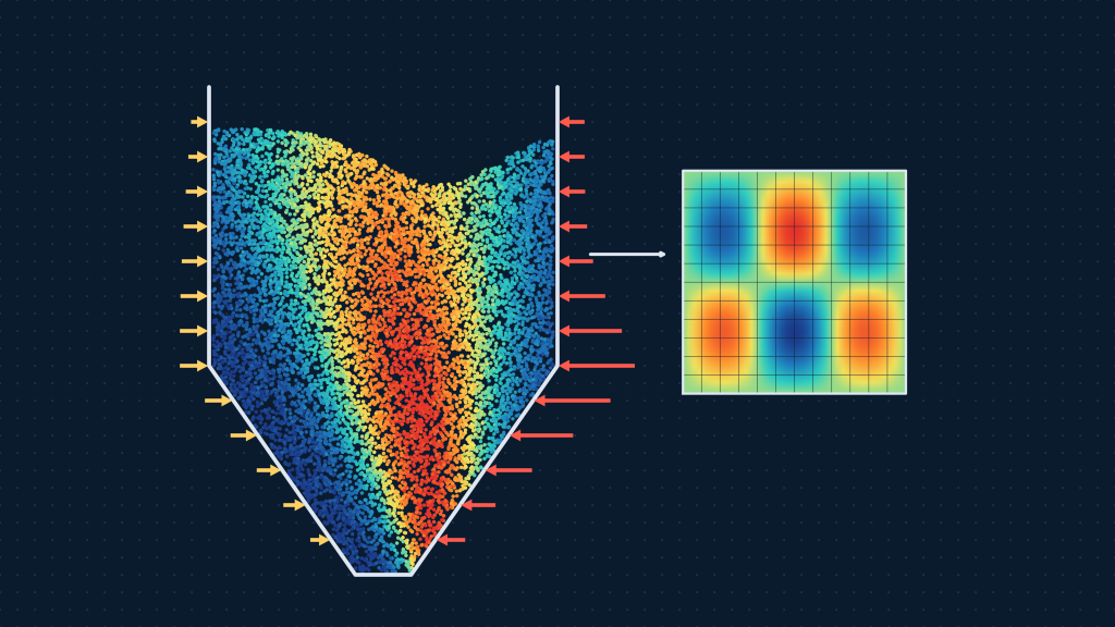
Uneven material flow occurs when material leaves the bin faster on one side than the other. Common causes include off-center or multiple outlets (such as a trouser leg discharge), an asymmetric feeder or gate arrangement, off-center filling that builds a sloped surface, and changes in material condition such as moisture, fines content or segregation. When flow concentrates in one region, a flow channel forms and the surrounding material shears against the wall or against stagnant material.
That has three structural consequences:
- Asymmetric wall pressure. Normal pressure and wall shear stress differ around the circumference and along the height of the bin. One quadrant can carry much more load than the opposite one.
- Eccentric loading. The resultant of the material load no longer acts through the centerline of the structure. The shell, hopper and supporting members are loaded unevenly, which adds bending and local compression to what was designed as a mostly axial and hoop-loaded system.
- Pressure peaks at transitions. Pressure is often highest where the bin changes geometry, for example at the junction between the vertical wall and the hopper, and where flow switches from mass to funnel behavior.
Thin-walled steel shells are efficient, but they are sensitive to local compression and imperfections. When uneven pressure combines with wall thinning from corrosion or abrasion, out-of-roundness, or loads applied from the roof, a panel can lose stability and buckle. Buckling is rarely a gradual process: once a local region starts to deform, stiffness drops and load redistributes to neighboring areas. That is why bin wall deformation should be treated as a warning sign and investigated rather than monitored indefinitely.
Simplified code-based methods and classical continuum approaches are valuable for standard geometries and symmetric discharge. They are less reliable for asymmetric discharge and complex hopper profiles, which is where advanced simulation becomes the more appropriate tool.
What DEM Simulation Can Reveal
The discrete element method models bulk material as a large number of individual particles. Each particle moves according to Newton’s laws, and forces arise wherever particles touch each other or touch the bin walls. Because the material is represented as discrete bodies rather than a smooth continuum, DEM can reproduce behaviors that matter in bins and hoppers: flow channeling, arching and ratholing, segregation, stagnant zones, and the way a flow pattern changes as the fill level drops.
From a bin design and assessment perspective, a DEM bulk material flow simulation can provide:
- Flow patterns and velocity fields, showing whether the bin discharges as mass flow or funnel flow and where flow is concentrated.
- Normal pressure and shear stress distributions on the walls, resolved by location and by time during filling, holding and discharge.
- The effect of operating conditions, such as fill level, outlet configuration and discharge sequence, on wall loads.
- Load cases that are difficult to define by hand, such as a single active outlet on a multi-outlet bin.
Capabilities and limitations
DEM is powerful, but it is a model, and its output is only as good as its inputs and assumptions. Engineers should keep these points in mind:
- Particle representation. Real material has irregular shapes and a wide size range. Simulating every particle is often impractical, so models use simplified shapes or scaled (coarse-grained) particles. This is a modelling decision that needs to be justified and tested.
- Contact parameters matter. Predicted flow and pressure depend on friction, stiffness and restitution values that are not always easy to measure.
- Time-dependent behavior. Cohesion, moisture effects, consolidation over time and material degradation are difficult to capture and often need dedicated calibration.
- Computational cost. Large bins with fine particles take significant computing time, so the scope of each simulation (which load cases, which fill levels) has to be chosen carefully.
- It is a load tool, not a structural verdict. DEM tells you what the material does. It does not, on its own, tell you whether the structure can carry it.
Used with these limits in mind, DEM provides wall load information that simplified methods cannot, particularly for non-axisymmetric conditions.
What Data Is Needed for a Reliable DEM Model?
A DEM model is built from four groups of information. The more of this that is measured rather than assumed, the more confidence you can place in the result.
- Geometry. The internal profile of the bin and hopper, including the cylindrical shell, hopper transitions, outlet size and position, and any internal features such as liners, baffles or feeders. Where the structure has deformed or lost thickness, as-built or measured geometry is more useful than design drawings.
- Material properties. Bulk density, particle size distribution, particle shape, moisture, and cohesion where relevant. For coarse materials such as lump coal or ore, particle size relative to outlet size strongly influences flow.
- Operating conditions. Fill levels, filling method and location, discharge rate and sequence, which outlets are active, and the range of conditions that the bin actually experiences. A model run at one fill level may miss the governing load case.
- Contact parameters. Particle-to-particle and particle-to-wall friction, contact stiffness, restitution and, for cohesive materials, adhesion. These values link the digital particles to the real behavior of the material.
Calibration versus validation
These two terms are often used interchangeably, but they are different steps:
- Calibration adjusts model parameters so that the simulation reproduces a known test result. A typical example is tuning friction and stiffness values until the simulated angle of repose or a shear test result matches the measured one.
- Validation checks the calibrated model against independent data that was not used to tune it, such as measured discharge rate, observed flow pattern or measured wall pressure in a comparable bin. Validation shows whether the model can predict behavior rather than just replicate the tests it was fitted to.
A model that has been calibrated but never validated can still be useful for comparing options, but its absolute pressure values deserve more caution. The same logic applies to thermal and structural models; our article on thermal design validation explains how test correlation and acceptance criteria support confidence in a numerical model.
From DEM Simulation to Structural FEA
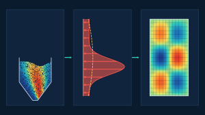
DEM answers “what load?”. Structural FEA answers “what does that load do to the steel?”. A reliable assessment links the two.
In practice, the workflow is:
- Extract wall loads from DEM. Normal pressure and shear stress are recorded on the bin and hopper surfaces for each relevant load case, and processed (averaged over suitable areas and time windows) so they are usable and not dominated by numerical noise.
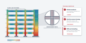
- Map the loads onto the structural model. The pressure and shear distributions are applied to the FEA model of the shell, hopper, stiffeners and supports. The structural model includes the as-built or as-assessed condition, for example reduced wall thickness due to corrosion or erosion, or measured out-of-roundness.
- Run the structural analyses. Stress and deformation analysis shows where the structure is highly utilized. Buckling analysis identifies the load level at which local or global instability occurs, usually reported as a buckling load factor relative to the applied load.
- Assess against the design basis. Results are checked against the relevant design standard, and sensitivity checks are run for the parameters that matter, such as wall thickness or load magnitude.
DEM alone does not establish structural safety. A DEM model can show very high wall pressure in a region, but whether that pressure is acceptable depends on the geometry, thickness, stiffening, material and imperfections of the wall, none of which DEM evaluates. Likewise, a structural FEA model is only as good as the load it is given. The two methods are complementary, and the value comes from connecting them in a documented, traceable way. For the broader question of when to use structural versus fluid simulation methods, see our guide on FEA vs CFD: key differences, applications, and how to choose the right simulation method.
Where the result will inform repair, modification or continued operation, formal design verification against the governing standard is the step that turns analysis results into an engineering decision. Readers who want an overview of how numerical tools fit together can also read our introductions to mechanical engineering simulation and what simulation software is and how it is used.
Case Study: PCI Bin Design Modification for BlueScope Steel
Avesta applied this DEM-to-FEA approach on a PCI (pulverized coal injection) coal bin at BlueScope Steel’s Port Kembla operations in New South Wales, Australia.
The problem. The NSBF PCI coal bin had experienced localized buckling in the bin wall quadrant adjacent to the trouser leg discharge. BlueScope needed to understand the load acting on the bin wall, in particular the eccentric load caused by discharge through a single trouser leg, and to verify proposed bin wall design modifications that BlueScope had developed from its initial structural analysis.
Role of load assessment. Because discharge occurs through a single trouser leg, the wall pressure is not uniform. Defining the eccentric normal pressure and shear stress distribution was therefore the foundation for any credible structural check.
What the engineering assessment involved:
- A bulk material flow analysis using DEM simulation of the bin, using the bin and hopper internal profile with single trouser leg discharge flow and a lump coal bulk density of 800 kg/m³.
- Determination of normal pressure and shear stress distributions along the bin and hopper walls for the operating levels and conditions specified by BlueScope.
- A strength and buckling assessment using structural FEA, applying the DEM-derived pressure and shear distributions to verify structural integrity in accordance with the Australian steel structures standard AS 4100.
- Determination of deflections and stresses in structural components, and the minimum buckling load factor, considering corroded and eroded wall thickness and the proposed design modifications.
Outcome. Avesta determined the most likely cause of the bin wall buckling deformation, taking into account wall erosion, eccentric roof bulk material loading and out-of-roundness. The assessment also established limiting roof loads and wall thickness, including the bin wall design modifications, to enable continued operation of the PCI coal bin, considering post-buckling roof load and wall thickness with and without the modifications.
The project shows why the two methods need each other: DEM provided the eccentric wall loads that a symmetric assumption would not have captured, and structural FEA translated those loads into stresses, deflections and a buckling margin that could be assessed against a standard. You can read the full project summary on the PCI Bin Design Modification project page. Where buckling or deformation has already occurred, a structured investigation such as root cause failure analysis helps separate load effects from material loss and geometric imperfection. Our comparison of RCA vs RCFA explains how to choose the right investigation method.
When Should You Use DEM Simulation?
Simplified assessment methods remain appropriate for many bins, particularly well-understood geometries with symmetric discharge and a material that has been characterized. Advanced simulation is more appropriate when:
- Discharge is asymmetric, for example single or partial outlets on a multi-outlet bin, off-center feeders, or eccentric filling.
- The bin has shown distress, such as buckling, bulging, cracking or accelerated wear, and the load is not understood.
- The geometry is complex, with unusual hopper transitions, internal features or non-standard profiles.
- Operating conditions have changed, such as higher fill levels, different material, new discharge sequences or increased throughput.
- Walls have lost thickness and a defensible, case-specific assessment is needed to decide on repair, modification or continued operation.
- A modification is proposed and its effect on both flow and structure must be demonstrated before it is built.
Information needed to start
To scope a project efficiently, it helps to have:
- Drawings or measurements of the bin, hopper and outlet arrangement, including any known deformation or thickness data.
- Material details: type, bulk density, particle size, moisture and any available flow property test results.
- Operating information: fill levels, filling and discharge methods, and the conditions you want assessed.
- Inspection history, photographs and any previous analysis reports.
- The design standard or acceptance criteria that apply to the structure.
Industries that routinely deal with these conditions include steel, mining and resources and minerals processing, where large storage bins, hoppers and chutes handle abrasive, heavy material every day.
Frequently Asked Questions
What is DEM simulation?
DEM (discrete element method) simulation is a numerical technique that models bulk material as a large number of individual particles and calculates the contact forces between them and with surrounding surfaces. It is used to study flow behavior, blockages, segregation and the loads that bulk solids apply to equipment such as bins, hoppers and chutes.
Can DEM predict wall pressure in a hopper?
Yes. DEM can estimate normal pressure and wall shear stress at different locations and times during filling, storage and discharge, including non-uniform and eccentric patterns that simplified methods struggle to represent. The reliability of the predicted pressures depends on the quality of the geometry, material data and contact parameters, and on whether the model has been calibrated and validated.
What is the difference between DEM and FEA?
DEM models the motion and forces of discrete particles, which makes it suitable for bulk material behavior. FEA models a continuous structure divided into finite elements, which makes it suitable for stress, deformation and buckling of steel components. For a bin, DEM typically defines the load and FEA evaluates the structural response to that load. For a broader comparison of simulation methods, see our article on FEA vs CFD.
Can DEM identify buckling risk?
DEM can identify the conditions that raise buckling risk, such as concentrated or eccentric wall pressure, but it does not calculate buckling itself. Buckling risk is assessed by transferring the DEM-derived loads into structural FEA, which determines stresses, deflections and buckling load factors for the actual wall geometry and thickness, and then checking the results against the relevant design standard.
Talk to Avesta About Bulk Material Flow and Structural Assessment
If you are dealing with uneven discharge, unexplained wall deformation or a proposed bin modification, Avesta can help you understand the loads and assess the structure. Our team combines bulk material flow simulation with structural FEA and design verification to give you a defensible answer. Contact Avesta Consulting to discuss your bin or hopper challenge, or explore our advanced simulation services.