A thermal model that predicts 82 °C at a critical component is not evidence that the component will run at 82 °C. It is a prediction. A thermocouple that reads 85 °C during a test is not evidence either, until someone can say what the sensor uncertainty was, what conditions the test represented and whether the model was ever set up to match them.
Thermal design validation is the discipline of connecting those two things. Done well, it produces a chain of evidence that runs from a written requirement through calculation, simulation and test to an acceptance decision that someone can defend. Done badly, it produces a colourful contour plot, a table of thermocouple readings and an argument about which one to believe.
This article assumes you already know the heat transfer fundamentals and have used CFD or FEA. Instead it focuses on the structure of the evidence chain. If you want the wider picture of how analysis fits into design, see our guide to simulation-driven design.
What Does Thermal Design Validation Prove?
Validation proves that a thermal design will meet its stated requirements in service, with a quantified level of confidence. That is a narrower and more useful claim than “the model is accurate”. A model can be accurate over the conditions tested and still say nothing about the worst case the equipment will actually see.
Verification vs Validation vs Qualification
The three terms are often used interchangeably, and that is where many validation plans go wrong.
- Verification asks whether the model was built and solved correctly: are the equations implemented properly, is the mesh adequate, does energy balance close?
- Validation asks whether the model represents reality well enough for its intended use, which can only be answered by comparison with test data.
- Qualification asks whether the hardware itself survives its specified environment. It is a test-based demonstration on the product and does not depend on the model at all.
A model can be perfectly verified and still invalid, for example if its boundary conditions do not reflect how the equipment is installed. Standards such as ASME V&V 20 frame this distinction formally for computational fluid dynamics and heat transfer, and are a useful reference when a client or regulator asks how credibility was established.
Requirements, Predictions and Evidence
Every claim in a validation package should trace in three steps: a requirement (for example, “shell surface temperature must not exceed the specified limit at rated load”), a prediction (what the verified model says) and evidence (what the test shows, with uncertainty). If any link is missing, the claim is an opinion. The V-model below shows how these links stack up, with each verification step on the left paired with the evidence that closes it on the right.
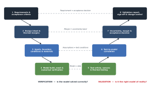
The horizontal pairings are the important part. Each step on the left is only closed when its partner on the right produces evidence against it. Numerical verification on its own never closes a requirement.
Build a Validation Plan
The validation plan should be written before any test is run and before the model is tuned. Writing it afterwards invites the plan to be shaped around whatever the results happened to show.
Critical Thermal Requirements and Margins
Start by listing the requirements that actually drive design decisions: maximum component and surface temperatures, allowable gradients, transient limits such as time to reach temperature, and heat loss or duty targets. For each, record the limit, the required margin and the operating case that governs it. Not every temperature in the model needs validating. Focus effort where a wrong prediction would change a decision.
Test Articles, Boundary Conditions and Instrumentation
Decide early whether the test article is the full product, a representative section or a purpose-built rig. Each choice changes what the correlation can legitimately claim. Then define the boundary conditions the test must reproduce or measure: ambient temperature, airflow, heat input, insulation condition and contact resistances. If a boundary condition cannot be controlled, it must be measured, because it becomes an input to the model when you correlate.
Analytical and Numerical Verification
Verification is complete when you can show the model solves its own equations correctly. It is quicker and cheaper than testing, so it should be finished before any hardware is instrumented.
Mesh/Time-Step Independence and Energy Balance
- Refine the mesh, and for transient cases the time step, until key outputs change by less than an agreed tolerance. A grid convergence index (GCI) is a common way to report the residual discretisation error.
- Check the global energy balance. Heat in, heat stored and heat out should close within a small percentage. An imbalance points to a boundary condition error long before it shows up as a strange temperature.
- Confirm that solver convergence criteria are tight enough for temperature, not just for residuals.
Benchmark Cases and Independent Calculations
Run the same model set-up on a simplified case with a known analytical or published solution, and hand-check the governing calculation independently. This is where errors in units, material property tables and sign conventions tend to surface. Where a design verification review is required, this step is the natural handover point to a second engineer. Our independent design verification service is built around exactly this kind of checking against relevant standards and project requirements.
Thermal Testing Methods
Steady-State, Transient and Thermal-Vacuum Tests
Steady-state tests are the simplest to correlate, because they remove heat capacity from the comparison and isolate conductance and boundary conditions. Transient tests add thermal mass and time dependence, and are essential when a requirement is about heat-up time, cycling or a duty profile. Thermal-vacuum testing removes convection to isolate conduction and radiation, which is the standard route for space hardware and useful for any design where radiation dominates. Choose the method that exposes the parameter you are least sure of, not the one that is easiest to run.
Sensor Placement, Calibration and Uncertainty
- Place sensors where the model is most sensitive and where requirements bite, including at least one location in a nominally boring region to check the far field.
- Calibrate the measurement chain, not just the sensor. Data logger, cold-junction compensation and wiring all contribute error.
- Quantify the installation error. Thermocouples attached to a surface can read differently from the true surface temperature, particularly with poor contact or high heat flux.
- Record an uncertainty for every channel. Standard-grade thermocouples, for example, are typically specified to a couple of degrees or a fraction of a percent of reading, which matters when a model is being compared to within a few degrees.
Test-to-Model Correlation
Correlation Metrics and Parameter Updating
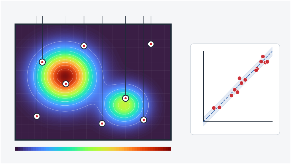
Compare predicted and measured values at every instrumented location, then summarise the result with metrics that are agreed in advance: mean error to show bias, standard deviation or RMS error to show scatter, and the maximum error at the locations that govern a requirement. Plot predicted against measured with the uncertainty band, as in the cover image, so a reviewer can see at a glance whether points sit inside the band.
When the model does not match, update only those parameters that are genuinely uncertain and physically plausible to change, such as contact conductance, effective emissivity or a poorly known convection coefficient. Record every change, and its reason.
Avoiding Over-Tuning the Model
A model can always be tuned to match one test. The danger is that it then matches only that test. Guard against this in three ways: keep a hold-out test case that the tuned model has never seen, keep parameter changes within physically defensible ranges, and prefer changing one well-understood parameter over adjusting many at once. A model that predicts a second, different test case with no further tuning has earned much more trust than one that fits its calibration data perfectly.
Acceptance Criteria and Margin Assessment
Pass/Fail Thresholds and Uncertainty Bands
Correlation criteria and design acceptance criteria are different things, and both need to be set before results are known. Correlation criteria say when the model is good enough to trust. Acceptance criteria say when the design is good enough to release. Space thermal practice has traditionally used a band of a few kelvin on test-to-model temperature differences, but the right band depends on the requirement margin and the measurement uncertainty, so it should be justified rather than copied.
The practical rule is to include uncertainty in the decision. If the predicted temperature plus model and measurement uncertainty still sits below the limit, the requirement is met with margin. If the uncertainty band straddles the limit, the honest answer is “not demonstrated”, and the response is more data or more margin, not a narrower band.
| Outcome | What the evidence shows | Typical response |
| Pass with margin | Prediction plus combined uncertainty is below the limit | Release; record margin |
| Marginal | Uncertainty band straddles the limit | Reduce uncertainty, add test data or design margin |
| Fail | Prediction or test exceeds the limit | Redesign, then re-verify and re-validate |
| Model not valid | Correlation criteria not met | Investigate discrepancy before using the model for acceptance |
Hotspots, Transients and Worst-Case Conditions
Validation at nominal conditions does not validate the worst case. Confirm which case governs, whether that is peak ambient, minimum airflow, end-of-life insulation or a transient overshoot, and make sure either the test reached it or the model has been validated well enough to extrapolate to it. Hotspots deserve particular attention, since small local errors in conductance or heat flux can move a peak temperature by more than the average error suggests. A sensitivity study on the top few inputs will show which uncertainties actually move the answer.
Validation Report and Change Control
Evidence Traceability and Deviations
The validation report should let a reviewer who was not in the room retrace every conclusion: requirement, model version, inputs, verification results, test set-up, sensor uncertainties, correlation results, parameter changes, and the acceptance decision. Record deviations honestly, including any test that did not go to plan, and state how each was dispositioned. Where a discrepancy cannot be explained, structured investigation methods such as those in our guide to common RCFA tools and techniques help separate a modelling error from a measurement error or a genuine design problem.
When Design Changes Require Re-Validation
Validation applies to a specific design, model and set of conditions. Changes to materials, geometry, insulation, heat load, operating envelope or boundary conditions can each invalidate part of the evidence chain. Put change control rules in the report: which changes need a check by analysis only, which need a partial re-test, and which reopen validation entirely. Without this, a validated design slowly drifts away from the thing that was actually tested.
FAQ
What is thermal design validation?
It is the process of demonstrating, through verified analysis and test data, that a thermal design will meet its requirements in service, with quantified uncertainty and a documented acceptance decision.
How do you correlate a thermal model with test data?
Run the verified model under the measured test conditions, compare predictions with measurements at every sensor, summarise bias and scatter against pre-agreed criteria, then update only uncertain, physically plausible parameters. Confirm the result on a separate test case.
What are acceptable thermal model correlation criteria?
There is no universal value. Criteria should be set from the requirement margin and measurement uncertainty. Some industries use a band of a few kelvin as a starting point, but the band must be justified for the specific design.
How should temperature sensor uncertainty be included?
Assign an uncertainty to each channel covering the sensor, the measurement chain and the installation, combine it with model uncertainty, and apply the combined band when comparing against both the correlation criteria and the design limit.
If you need an independent view on whether a thermal design is demonstrated, or help correlating a model to test data, our team can provide independent thermal assessment and test-to-model correlation support through our advanced simulation services. We regularly work on high-temperature equipment, including high temperature pressure vessels. To discuss your project, get in touch with our team.
Related reading: What Is Simulation-Driven Design? Benefits, Process and Real-World Engineering Applications · Common RCFA Tools: Methods and Techniques Used in Root Cause Failure Analysis