Cracks are among the most serious defects found in industrial equipment and engineering structures. A small crack may appear harmless during an inspection. However, repeated loading can cause it to grow over time.
Eventually, the crack may reach a critical size. At that point, the remaining section may no longer support the applied load. Failure can then occur rapidly and with little warning.
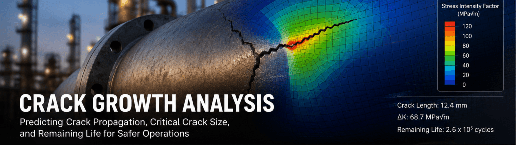
Crack growth analysis helps engineers understand this process. It predicts how quickly a crack may propagate under real operating conditions. It can also estimate when the crack could become unsafe.
This information supports better decisions about inspection, repair, maintenance, and equipment replacement. As a result, organisations can reduce the risk of unexpected failure while avoiding unnecessary shutdowns.
Crack growth analysis is especially important for pressure vessels, pipelines, mining equipment, offshore structures, rotating machinery, welded connections, and other safety-critical assets.
The method combines several sources of information. These may include inspection measurements, operating loads, material properties, fracture toughness, crack geometry, environmental conditions, and finite element analysis.
When engineers use these inputs correctly, they can estimate the remaining life of a cracked component. They can also establish suitable inspection intervals and determine whether continued operation is acceptable.
What Is Crack Growth Analysis?
Crack growth analysis is an engineering method used to predict how an existing crack will extend under applied loading.
The analysis normally begins with a known or assumed crack. Engineers define its size, shape, depth, orientation, and location. They then calculate the forces that drive crack propagation.
These forces depend on the applied stress and the local geometry. They also depend on the material’s resistance to crack growth.
The analysis usually answers several important questions:
- Will the crack remain stable?
- How quickly will it grow?
- In which direction will it propagate?
- What crack size will become critical?
- How many operating cycles remain?
- When should the next inspection occur?
- Is a repair required?
- Can the component remain in service safely?
Crack growth analysis differs from a basic strength calculation. A conventional stress assessment often assumes that the component contains no significant defects.
However, real industrial assets may contain weld discontinuities, corrosion pits, machining marks, inclusions, or fatigue cracks. Therefore, engineers must understand how these defects affect structural integrity.
Crack growth analysis provides this defect-based perspective. Instead of asking only whether the nominal stress is acceptable, it asks whether a specific crack can grow to an unsafe size.
Why Crack Growth Analysis Matters
A crack does not automatically mean that a component must be replaced. Some cracks may remain stable for a long period. Others may grow quickly under cyclic loading.
The main challenge is determining which situation applies.
Without engineering analysis, maintenance teams may rely on assumptions. They may remove safe equipment too early. Alternatively, they may continue operating a component that has very little remaining life.
Both decisions can be costly.
Crack growth analysis provides a more reliable basis for decision-making. It connects inspection findings with material behaviour, loading history, and fracture mechanics.
Consequently, engineers can move from simple defect detection to a full structural integrity assessment.
Preventing Unexpected Failures
The most important purpose of crack growth analysis is failure prevention.
Many industrial failures begin with small defects. These defects may form during manufacturing, welding, installation, or service. At first, they may not reduce the component’s load capacity significantly.
However, repeated stress can extend the crack. Each operating cycle may cause a small amount of growth.
As the crack becomes larger, the stress intensity at its tip increases. The crack may then grow faster. Eventually, it can reach an unstable condition.
At that stage, final fracture may occur during normal operation. The applied load does not need to exceed the original design load.
Crack growth analysis identifies this risk before the crack becomes critical. It allows engineers to estimate how much time remains for inspection, repair, or replacement.
Extending Equipment Service Life
Replacing equipment as soon as a crack appears can be unnecessarily expensive.
Industrial assets often have high replacement costs. They may also require long manufacturing lead times and major plant shutdowns.
A properly completed crack assessment can show whether the detected defect remains acceptable for a controlled period.
For example, the analysis may demonstrate that the crack will remain below the critical size for several million cycles. The operator can then continue service while monitoring the defect.
This approach can extend equipment life without reducing safety. However, the decision must rely on accurate data and suitable safety factors.
Service life extension should never depend on visual judgement alone. Engineers must consider crack size, crack growth rate, material toughness, loading, environment, and inspection reliability.
Supporting Inspection Planning
Inspection programs often use fixed time intervals. For example, a component may receive ultrasonic testing every 12 months.
However, a calendar-based interval may not reflect the real crack growth risk.
A crack in a lightly loaded component may grow very slowly. In contrast, a similar crack in a highly cycled component may grow much faster.
Crack growth analysis helps establish inspection intervals based on predicted damage.
Suppose an existing crack requires four years to reach the maximum allowable size. Engineers may select a much shorter inspection interval, such as six or twelve months.
This interval provides enough time to detect unexpected growth before the defect becomes dangerous.
Therefore, the inspection schedule becomes risk-based rather than arbitrary. It reflects the actual material, geometry, load history, and crack behaviour.
Crack Initiation vs Crack Propagation
Crack initiation and crack propagation are related processes. However, they are not the same.
Crack initiation describes the formation of a small crack in material that was previously considered uncracked. Initiation often occurs at a local stress concentration.
Common initiation locations include:
- Weld toes
- Weld roots
- Bolt holes
- Keyways
- Sharp corners
- Thread roots
- Corrosion pits
- Surface scratches
- Inclusions
- Machining marks
- Sudden changes in section thickness
During initiation, repeated loading creates local material damage. Small slip bands or microcracks may form. These microcracks can then combine into a larger engineering crack.
Crack propagation begins after a detectable crack already exists. The crack extends by a small amount during each significant load cycle.
Traditional fatigue analysis may estimate the total life required for crack initiation and final failure. In comparison, fracture-mechanics-based crack growth analysis focuses on the propagation phase.
This distinction matters when an inspection has already detected a crack. At that point, engineers should not assume that the component still has its full design fatigue life.
Instead, they must assess the existing crack directly.
For some components, crack initiation consumes most of the fatigue life. For other components, propagation may represent a large part of the service life.
The balance depends on material, surface condition, loading, geometry, and environment.
How Cracks Grow Under Cyclic Loading
Cyclic loading occurs when stress changes repeatedly over time.
The load does not need to reverse from tension to compression. A pressure vessel that repeatedly moves between low and high pressure experiences cyclic loading. A conveyor support that vibrates during operation also experiences repeated stress.
During each cycle, the crack tip opens and closes. The local stress at the tip is much higher than the nominal stress in the component.
This concentrated stress creates a small zone of material damage. As the cycle repeats, the crack advances.
The amount of growth per cycle may be extremely small. However, equipment can experience thousands or millions of cycles during service.
Therefore, even microscopic growth can become significant over time.
Crack growth often accelerates as the crack becomes larger. This occurs because a longer crack generally produces a higher stress intensity under the same applied load.
The growth process is not always smooth. Variable loading, overloads, underloads, residual stress, crack closure, and environmental effects can change the rate.
For this reason, engineers should use a realistic loading history whenever possible.
Fatigue Loading
Fatigue loading is one of the main causes of crack growth in engineering components.
Fatigue occurs when repeated stress causes progressive damage. Importantly, the maximum stress may remain below the material’s yield strength.
Examples of fatigue loading include:
- Pressure cycles in vessels and pipelines
- Start-up and shutdown cycles
- Rotating shaft loads
- Conveyor vibration
- Wave loading on offshore structures
- Vehicle movement across bridges
- Thermal expansion and contraction
- Pump and compressor vibration
- Wind-induced oscillation
- Repeated lifting operations
- Impact from bulk material
Engineers describe a fatigue cycle using maximum stress, minimum stress, stress range, and stress ratio.
The stress range is the difference between maximum and minimum stress. It strongly influences fatigue crack growth.
The stress ratio compares minimum stress with maximum stress:
R = minimum stress / maximum stress
A high tensile mean stress can keep the crack open for more of the cycle. As a result, the crack may grow faster.
In contrast, compressive parts of the cycle may close the crack and reduce the effective driving force.
Actual industrial loading is often irregular. Therefore, engineers may need to process measured load data before completing the crack growth assessment.
Methods such as rainflow cycle counting can convert a complex load history into a series of representative fatigue cycles.
Crack Growth Mechanisms
Cracks can grow through several mechanisms. The governing mechanism depends on material, stress, temperature, and environment.
Fatigue Crack Growth
Fatigue crack growth occurs under repeated or fluctuating loading.
The crack advances in small increments. Microscopic marks called fatigue striations may form on the fracture surface in some materials.
Fatigue growth often begins slowly. However, the rate usually increases as the crack becomes longer.
Corrosion Fatigue
Corrosion fatigue occurs when cyclic loading acts together with a corrosive environment.
The environment damages the material near the crack tip. It may also reduce the crack growth threshold.
As a result, cracks can grow faster than they would in dry air.
Corrosion fatigue can affect pipelines, offshore structures, chemical equipment, mining assets, marine components, and water-processing equipment.
Stress Corrosion Cracking
Stress corrosion cracking requires a susceptible material, tensile stress, and a specific environment.
The tensile stress may come from operating loads or welding residual stress. In some cases, the applied stress remains relatively constant rather than cyclic.
Examples include chloride stress corrosion cracking in stainless steel and caustic cracking in certain process environments.
Stress corrosion cracks may branch and grow with limited visible deformation.
Hydrogen-Assisted Cracking
Hydrogen can enter a metal during manufacturing, welding, corrosion, chemical processing, or cathodic protection.
The hydrogen can reduce ductility and fracture resistance. High-strength steels are often especially sensitive.
Hydrogen-assisted cracking may produce sudden failure. Therefore, engineers must assess the service environment as well as the mechanical load.
Thermal Fatigue
Thermal fatigue occurs when repeated temperature changes create cyclic thermal stress.
Different parts of a component may heat or cool at different rates. This creates expansion mismatch and local stress.
Thermal fatigue commonly affects furnaces, pressure equipment, piping, exhaust systems, heat exchangers, and high-temperature process equipment.
Final Fracture
Fatigue crack growth does not continue indefinitely.
Eventually, the remaining uncracked section becomes too small to support the applied load. Alternatively, the crack-tip driving force may exceed the material’s fracture resistance.
At that point, final fracture occurs.
Final fracture may be ductile or brittle. The result depends on material toughness, temperature, thickness, stress state, loading rate, and constraint.
In a ductile final fracture, the remaining section may yield and tear. Visible deformation may occur before complete separation.
In a brittle final fracture, the crack may become unstable with little plastic deformation. Failure can then occur very quickly.
The transition from stable crack growth to final fracture is a critical part of the assessment.
Engineers must calculate a limiting crack size. They must then apply suitable safety margins when defining the allowable crack.
The maximum acceptable crack is normally smaller than the theoretical critical size. This approach accounts for uncertainty in inspection, loading, material properties, and modelling.
Key Factors Affecting Crack Growth
Crack propagation depends on several interacting factors. An accurate assessment must consider each one.
Stress Range
Stress range is a major driver of fatigue crack growth.
A larger stress range usually produces a larger stress intensity range at the crack tip. Therefore, the crack often grows faster.
The stress used in the calculation should include more than simple nominal stress.
Engineers may need to consider:
- Membrane stress
- Bending stress
- Thermal stress
- Dynamic stress
- Vibration stress
- Residual stress
- Pressure stress
- Local structural stress
- Secondary stress
- Stress from misalignment
Ignoring a significant stress source can lead to an unsafe life prediction.
Load sequence also matters. A single overload may accelerate or temporarily slow later crack growth, depending on the material and conditions.
Therefore, a realistic load spectrum is more reliable than one constant stress range.
Material Properties
Different materials have different resistance to crack propagation.
Engineers often obtain fatigue crack growth properties from laboratory testing, recognised standards, technical literature, or project-specific material tests.
Important material parameters include:
- Fatigue crack growth constants
- Fracture toughness
- Yield strength
- Ultimate tensile strength
- Elastic modulus
- Crack growth threshold
- Temperature-dependent properties
- Environmental crack growth data
Material condition also matters.
Heat treatment, welding, cold work, aging, and manufacturing processes can change crack growth behaviour. Weld metal and heat-affected zones may perform differently from the parent material.
When project-specific test data is available, it can improve the assessment. However, the data must represent the correct material and environment.
Environmental Conditions
The operating environment can significantly increase crack growth.
Corrosive fluids may attack the crack tip. Moisture, salt, chemicals, hydrogen, and elevated temperature can all influence material behaviour.
A crack growth curve measured in laboratory air may not represent service in seawater or a corrosive process fluid.
Temperature can also affect both crack growth rate and fracture toughness.
At low temperature, some steels lose toughness. At high temperature, creep and oxidation may interact with fatigue.
Therefore, engineers should identify the real service environment before choosing material data.
Environmental conditions may include:
- Seawater exposure
- Chlorides
- Acidic fluids
- Wet hydrogen sulphide
- Hydrogen service
- High humidity
- Elevated temperature
- Low-temperature operation
- Thermal cycling
- Corrosion under insulation
- Process contamination
Protective coatings and corrosion control can reduce environmental exposure. However, engineers should not assume that these systems remain perfect throughout service.
Geometry and Stress Concentrations
Component geometry changes the stress field around a crack.
A crack near a nozzle, hole, weld, corner, attachment, or thickness transition may experience a higher driving force than a crack in a simple flat plate.
The crack shape also matters.
Common crack geometries include:
- Surface cracks
- Through-wall cracks
- Embedded cracks
- Corner cracks
- Circumferential cracks
- Axial cracks
- Semi-elliptical cracks
- Cracks at weld toes
- Cracks at weld roots
Surface cracks often grow in both depth and length. Their shape can change during propagation.
Geometry correction factors help account for these effects in standard solutions. However, complex structures may require numerical modelling.
Local stress concentrations must also be included. A low nominal stress can still create a high crack-tip driving force near a sharp detail.
Methods Used in Crack Growth Analysis
Engineers can use several methods to assess crack propagation.
The correct method depends on component complexity, available data, crack size, material behaviour, and required accuracy.
Fracture Mechanics Assessment
Fracture mechanics provides the theoretical foundation for crack growth analysis.
It studies the behaviour of materials that contain cracks or crack-like defects.
Linear elastic fracture mechanics often uses the stress intensity factor, K. This parameter describes the local stress field near a crack tip.
For cyclic loading, engineers calculate the stress intensity factor range:
ΔK = Kmax − Kmin
The value of ΔK depends on applied stress, crack size, and geometry.
A general form is:
ΔK = Y × Δσ × √(πa)
Where:
- Y is a geometry correction factor
- Δσ is the stress range
- a is the crack size
- ΔK is the stress intensity factor range
As the crack becomes larger, ΔK usually increases. Therefore, crack growth often accelerates.
Linear elastic fracture mechanics works best when plastic deformation near the crack tip remains limited.
When significant plasticity occurs, engineers may use elastic-plastic fracture mechanics. Parameters such as the J-integral or crack-tip opening displacement can then describe the crack-driving force.
A full fracture assessment may also compare the risk of fracture with the risk of plastic collapse.
Failure assessment diagrams provide one method for evaluating both conditions together.
Fatigue Crack Growth Models
Fatigue crack growth models relate crack extension to the applied loading.
One of the best-known models is Paris’ law:
da/dN = C(ΔK)^m
Where:
- da/dN is crack growth per cycle
- C and m are material constants
- ΔK is the stress intensity factor range
Paris’ law describes the stable middle region of fatigue crack growth.
However, it does not fully describe behaviour near the crack growth threshold or close to final fracture.
More advanced models can account for stress ratio, crack closure, threshold behaviour, and rapid growth near instability.
Examples include:
- Forman-type models
- Walker-type models
- NASGRO-type models
- Code-based crack growth relationships
- Project-specific fitted growth laws
The crack growth model can be integrated from the initial crack size to the limiting crack size.
In simple terms, the calculation adds the small amount of growth produced by each load cycle. It continues until the crack reaches the defined limit.
The result gives the predicted number of remaining cycles.
Engineers can then convert cycles into operating time. For example, a pressure cycle history may be converted into months or years of service.
The accuracy depends heavily on the input data. A sophisticated model cannot correct an unrealistic stress history or incorrect crack measurement.
Numerical Simulation and FEA
Standard fracture mechanics equations work well for many common geometries.
However, industrial equipment often contains complex shapes, multiple loads, contact conditions, welds, and nonlinear behaviour.
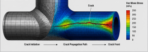
Finite element analysis can calculate the local stress field in these situations.
FEA can help engineers:
- Determine local stresses near the crack
- Calculate stress intensity factors
- Calculate J-integral values
- Model complex crack geometries
- Predict crack direction
- Evaluate mixed-mode loading
- Assess thermal and mechanical stress
- Include residual stress
- Simulate changing crack geometry
- Compare repair options
- Calculate critical crack size
Some numerical techniques allow the crack to extend through the model. The mesh may update as the crack grows.
Extended finite element methods can also represent crack growth without fully remeshing the geometry after each step.
However, detailed simulation requires careful validation.
The mesh near the crack tip must provide sufficient accuracy. Boundary conditions must represent the real structure. Loads must reflect service conditions.
Engineers should also compare numerical results with analytical solutions, measured data, or recognised benchmarks.
FEA does not remove the need for engineering judgement. Instead, it provides a more detailed method when simple solutions are not sufficient.
Combining Inspection Data with Crack Growth Modelling
Crack growth analysis becomes more valuable when engineers have inspection data from different dates.
For example, ultrasonic testing may show that a crack measured 8 mm in 2024 and 10 mm in 2025.
This history provides evidence of actual crack growth.
Engineers can compare the measured rate with the predicted model. They can then calibrate the material constants or review the assumed loads.
If measured growth is faster than predicted, the model may be missing an important factor. The cause could involve vibration, residual stress, corrosion, or an underestimated load.
If the measurements show little or no growth, the analysis may support continued monitored operation.
However, inspection uncertainty must be considered. A small difference between two readings may reflect measurement variation rather than real crack extension.
For this reason, inspection procedures should record crack location, orientation, length, depth, equipment settings, and measurement uncertainty.
Using the same qualified method and reference system improves comparison between inspections.
Crack Growth Analysis Applications
Crack growth analysis supports many industries. It is especially valuable where equipment experiences repeated loads or where failure would have serious consequences.
Pressure Vessels
Pressure vessels experience repeated pressure and temperature changes.
Cracks may develop at welded seams, nozzles, supports, attachments, repairs, and other stress concentration areas.
A crack growth assessment can determine whether a detected defect will remain stable during continued pressure cycles.
The analysis may include:
- Internal pressure
- External piping loads
- Thermal stress
- Start-up and shutdown cycles
- Weld residual stress
- Material toughness
- Crack depth and length
- Corrosion effects
- Minimum operating temperature
- Pressure-test conditions
Surface cracks may grow through the vessel wall. Once a crack becomes through-wall, leakage may occur.
In some cases, leakage may provide warning before rupture. However, engineers should never assume that leak-before-break behaviour will occur without assessment.
A pressure vessel crack assessment can support repair planning, inspection intervals, operating restrictions, and remaining life decisions.
Pipelines
Pipelines can contain manufacturing defects, weld defects, corrosion pits, dents, and service-induced cracks.
Pressure fluctuations cause cyclic stress in the pipe wall. Ground movement, temperature changes, vibration, and external loads may add further stress.
Cracks may run in the axial or circumferential direction.
Axial cracks are strongly influenced by internal pressure. Circumferential cracks may become critical under bending, ground movement, or thermal expansion.
Crack growth analysis can evaluate:
- Pressure-cycle fatigue
- Corrosion fatigue
- Stress corrosion cracking
- Cracks associated with dents
- Girth-weld defects
- Seam-weld defects
- Hydrogen-assisted cracking
- Remaining strength
- Critical crack dimensions
The results can help pipeline operators prioritise excavation, repair, pressure reduction, or further inspection.
Mining Equipment
Mining equipment operates under severe loading.
Structures may experience impact, vibration, variable payloads, abrasive wear, corrosion, and continuous operation.
Common crack locations include weld toes, support brackets, boom connections, chassis members, crusher frames, screens, conveyors, buckets, and lifting attachments.
A crack in mining equipment may grow under a complex load spectrum. The equipment may experience both high-frequency vibration and occasional heavy impact.
Crack growth analysis can use measured strain or acceleration data to define realistic loads.
FEA can then calculate stress at the cracked detail. Engineers can use the result to estimate remaining life and compare repair concepts.
This process supports planned maintenance. It also reduces the risk of a major failure in a remote or difficult-to-access location.
Offshore Structures
Offshore structures operate in demanding marine environments.
Wave loading creates millions of stress cycles. Wind, current, equipment loads, and platform movement add further variation.
At the same time, seawater increases the risk of corrosion fatigue.
Cracks may develop in welded tubular joints, braces, risers, mooring components, decks, cranes, and subsea equipment.
Inspection can also be difficult. Some areas require underwater access or remotely operated equipment.
Therefore, crack growth analysis plays an important role in inspection planning.
The model can estimate how a detected crack may grow between inspections. It can also identify the locations that require the greatest attention.
Environmental crack growth data is especially important offshore. Growth rates measured in dry air may not represent seawater conditions.
Rotating Machinery and Mechanical Components
Shafts, gears, rotors, blades, and couplings experience repeated stress during rotation.
A small crack can grow with every revolution. Therefore, the number of cycles can increase very quickly.
Crack growth analysis can assess defects near keyways, fillets, splines, holes, and surface damage.
The analysis may also consider centrifugal force, torsion, bending, vibration, and thermal stress.
Rotating equipment requires careful assessment because final fracture can release stored kinetic energy.
Monitoring methods such as vibration analysis may detect changes in behaviour. However, fracture mechanics is still needed to connect the crack size with the remaining life.
Crack Growth Analysis vs Traditional Inspection
Traditional inspection identifies the condition of a component at a specific moment.
It can locate cracks and measure their dimensions. However, inspection alone does not predict what will happen next.
A 5 mm crack may be acceptable in one component but dangerous in another.
The difference depends on load, material, geometry, fracture toughness, stress concentration, and environment.
Crack growth analysis adds a predictive layer.
Inspection answers:
“What is the crack size today?”
Crack growth analysis answers:
“How fast could it grow, and when could it become unsafe?”
The two methods should work together.
Inspection provides the real defect dimensions. Engineering analysis predicts future behaviour. Later inspections can then confirm whether the prediction remains accurate.
Traditional inspection also has detection limits.
Very small cracks may remain below the reliable detection threshold. Access restrictions, surface condition, geometry, and operator skill can affect accuracy.
Therefore, crack growth assessments should consider inspection capability. Engineers should not define an inspection plan that depends on reliably detecting a crack smaller than the chosen method can find.
Remaining Life Assessment and Maintenance Planning
Remaining life assessment estimates how long a component can operate before reaching a defined limit.
For a cracked component, the process often follows these steps:
- Define the current crack size.
- Confirm the crack location and orientation.
- Establish the operating load history.
- Calculate local stress.
- Select suitable material crack growth data.
- Calculate crack growth for each load cycle.
- Determine the critical or allowable crack size.
- Estimate the remaining number of cycles.
- Apply appropriate safety factors.
- Establish inspection or repair dates.
The result should not be treated as an exact failure date.
Every crack growth assessment contains uncertainty. Crack measurement, load prediction, material properties, residual stress, and environmental conditions may vary.
Therefore, engineers normally apply conservative assumptions and safety margins.
Maintenance teams can use the results to compare several options.
These may include:
- Immediate repair
- Continued operation with monitoring
- Reduced operating load
- Reduced pressure or temperature
- Increased inspection frequency
- Local reinforcement
- Weld repair
- Component replacement
- Operational changes
- Elimination of vibration
The best option depends on safety, cost, downtime, access, and regulatory requirements.
A well-planned assessment can prevent both unnecessary replacement and unsafe life extension.
Defining Critical and Allowable Crack Size
The critical crack size is the size at which fracture or another failure condition becomes possible under the assessed load.
This size depends on applied stress, material toughness, geometry, and failure mode.
A tougher material can usually tolerate a larger crack. A higher applied stress reduces the tolerable crack size.
The allowable crack size should remain below the theoretical critical crack size.
Engineers apply safety factors because the inputs are never perfectly known.
For example, the real crack may be slightly deeper than the inspection result. The actual stress may also exceed the calculated value during an upset condition.
Therefore, the assessment limit must provide a suitable margin.
In some cases, the limiting condition is not unstable fracture. Plastic collapse, leakage, excessive deformation, or code acceptance criteria may govern instead.
Engineers must evaluate all relevant failure modes.
Common Mistakes in Crack Growth Assessment
Crack growth analysis can provide valuable results. However, incorrect assumptions can create a false sense of security.
Using the Wrong Initial Crack Size
The assessment must use a realistic initial crack.
Using only the reported crack depth without considering measurement uncertainty may overestimate remaining life.
Engineers should review the inspection method, calibration, reporting format, and probability of detection.
Ignoring Crack Shape
A surface crack has both depth and length.
These dimensions may grow at different rates. Assuming that the crack keeps the same shape can produce inaccurate results.
The crack may also interact with nearby surfaces, welds, or geometric features.
Using Nominal Stress Only
Nominal stress may be much lower than the local stress at a weld, hole, attachment, or thickness transition.
The assessment should include relevant stress concentrations and secondary stresses.
Residual stress may also be important, especially in welded components.
Applying Inappropriate Material Data
Crack growth constants should represent the actual material and service conditions.
Data for a different alloy, heat treatment, temperature, or environment may not be suitable.
Overly optimistic average data can produce an unsafe result. Conservative lower-bound or upper-bound data may be more appropriate, depending on the parameter.
Ignoring Environmental Effects
Air-based fatigue data may underestimate growth in seawater, corrosive chemicals, hydrogen service, or elevated temperature.
The environment can influence both growth rate and fracture toughness.
Simplifying the Load History Too Much
A single constant stress range may not represent variable industrial loading.
Start-ups, shutdowns, impact events, overloads, vibration, and process changes can affect crack growth.
Whenever possible, engineers should use measured or well-supported load spectra.
Treating FEA as Automatically Accurate
A detailed model can still produce the wrong answer.
Poor mesh quality, unrealistic restraints, missing loads, or incorrect material properties can distort the result.
Engineers should verify the model against hand calculations, standard solutions, test data, or measured behaviour.
Ignoring Inspection Uncertainty
Inspection results are measurements, not exact values.
The method may underestimate crack depth or fail to identify connected defects.
The assessment should include suitable allowances for uncertainty.
Predicting Beyond the Valid Range of the Model
Paris’ law does not describe every stage of crack growth.
It may not capture threshold behaviour or rapid growth near final fracture.
The selected model must remain valid across the assessed crack size and loading range.
Failing to Update the Assessment
Operating conditions can change.
Higher production rates, new process fluids, added equipment, altered supports, or increased vibration may invalidate the original model.
Engineers should update the assessment when new inspections or operating data become available.
Confusing Calculation with Risk Management
A remaining life result does not replace inspection, monitoring, or maintenance control.
The calculation should form part of a wider integrity management plan.
Clear responsibilities, inspection dates, operating limits, and response actions must support the engineering result.
Best Practices for Reliable Crack Growth Analysis
A reliable assessment begins with good data.
Engineers should confirm the crack dimensions, material grade, operating history, geometry, and likely failure mechanism.
They should also identify uncertainties before selecting the analysis method.
The following practices improve reliability:
- Use qualified inspection methods.
- Include inspection uncertainty.
- Confirm the real loading history.
- Consider local and residual stresses.
- Use suitable material crack growth data.
- Account for the operating environment.
- Check all relevant failure modes.
- Validate FEA results.
- Apply suitable safety margins.
- Compare predictions with later inspections.
- Update the model when conditions change.
- Document assumptions clearly.
A multidisciplinary approach often gives the best result.
Inspection specialists understand detection limits. Materials engineers understand fracture behaviour. Operations teams understand load history. FEA engineers understand local stress and geometry.
Combining these perspectives reduces the risk of overlooking an important factor.
How Avesta Consulting Supports Crack Growth Assessment
Crack growth assessment requires more than one calculation.
A reliable study may involve inspection review, load assessment, material evaluation, fracture mechanics, fatigue modelling, and numerical simulation.
Avesta Consulting combines engineering analysis with measured data to evaluate crack behaviour in industrial components.
Depending on the project, the assessment may include:
- Review of crack inspection results
- Crack growth rate evaluation
- Paris’ law modelling
- Code-based fracture assessment
- Stress intensity factor calculation
- Critical crack length calculation
- FEA-based crack path prediction
- Remaining fatigue life assessment
- Inspection interval development
- Load and vibration evaluation
- Repair option comparison
- Structural integrity reporting
This integrated approach helps clients understand whether a crack requires immediate repair or controlled monitoring.
It also supports evidence-based decisions about continued operation, service life extension, and maintenance planning.
Frequently Asked Questions
What is the purpose of crack growth analysis?
The purpose is to predict how an existing crack may extend under service loading.
The analysis estimates growth rate, critical crack size, remaining cycles, and suitable inspection intervals.
How is crack growth rate calculated?
Engineers often calculate crack growth using fracture mechanics relationships.
Paris’ law is one common model. It relates crack growth per cycle to the stress intensity factor range.
More advanced models can account for stress ratio, threshold behaviour, and rapid growth near final fracture.
What is a critical crack size?
The critical crack size is the crack dimension at which the component may become unstable under the assessed load.
The actual allowable crack size should remain below this value and include suitable safety margins.
Can a cracked component remain in service?
In some cases, yes.
A component may remain in controlled service when engineering analysis shows that the crack is stable and has adequate remaining life.
However, continued operation usually requires defined inspection intervals and operating limits.
Does FEA replace crack inspection?
No.
FEA predicts stress and crack-driving forces. Inspection identifies the real crack size and condition.
The most reliable approach combines both methods.
Can crack growth analysis determine inspection intervals?
Yes.
Engineers can estimate the time required for a crack to grow from its current size to a defined allowable size.
They then select a shorter inspection interval that provides an appropriate safety margin.
What information is needed for crack growth analysis?
The assessment usually requires crack dimensions, geometry, material properties, operating loads, load cycles, temperature, environment, and fracture toughness.
Inspection history and measured strain or vibration data can improve the result.
Conclusion
Crack growth analysis is an essential tool for managing cracked industrial equipment and structures.
It moves the engineering decision beyond simple defect detection. Instead, it predicts how the crack may behave during future operation.
The assessment considers crack geometry, stress range, material properties, environmental conditions, fracture toughness, and loading history.
Fracture mechanics models can estimate crack growth under repeated loading. Meanwhile, FEA can calculate the crack-driving force in complex components.
When engineers combine analysis with reliable inspection data, they can estimate remaining life and establish risk-based inspection intervals.
This process helps prevent unexpected failures. It can also extend equipment life, reduce unnecessary replacement, and improve maintenance planning.
However, crack growth predictions depend on the quality of the inputs. Engineers must account for measurement uncertainty, variable loading, residual stress, and environmental effects.
The strongest approach combines inspection, fracture mechanics, fatigue analysis, numerical simulation, and practical engineering judgement.
For pressure vessels, pipelines, mining equipment, offshore structures, and other critical assets, this integrated method provides a clear path toward safer and more informed integrity decisions.