Pressure vessels are vital components in industries ranging from chemical processing to oil and gas, petrochemicals, and power generation. These vessels are designed to contain gases or liquids at pressures far above or below ambient levels, making their design and drafting critical for safety, compliance, and operational efficiency.
In this guide, we will explore pressure vessel drafting and drawing, covering ASME requirements, common symbols, software tools, case studies, and emerging trends in 3D modeling and digital transformation.
Understanding Pressure Vessel Drafting
Drafting is the process of creating detailed technical drawings that communicate the design intent of a pressure vessel. These drawings are essential for fabrication, inspection, and certification. While a design engineer focuses on calculations, stress analysis, and safety factors, the drafter translates these designs into precise, standardized drawings that manufacturers and inspectors can rely on.
A well-drafted pressure vessel drawing ensures:
-
Accurate fabrication according to design specifications
-
Compliance with safety and regulatory standards
-
Clear communication between engineering, fabrication, and quality teams
ASME Requirements for Pressure Vessel Drawings
The American Society of Mechanical Engineers (ASME) sets global standards for the design, fabrication, and inspection of pressure vessels. ASME codes, particularly ASME Section VIII Division 1 & 2, provide guidelines for drawings to ensure safety and consistency.
Key ASME Drawing Requirements:
-
Title Block: Must include the vessel name, drawing number, revision number, designer, checker, date, and project details.
-
Material Specifications: Indicate all materials used, including shell, head, nozzles, and supports.
-
Dimensions and Tolerances: Precise dimensions for diameter, thickness, and length of the vessel and components.
-
Design Pressure and Temperature: Must be clearly indicated for fabrication and testing purposes.
-
Weld Details: Include type, size, and welding process for all joints.
-
Nozzle and Flange Details: Placement, orientation, and dimensions for all openings.
-
Inspection Points: Locations for non-destructive testing (NDT), hydrostatic testing, and other quality checks.
Adhering to ASME standards not only ensures regulatory compliance but also reduces the risk of fabrication errors and operational failures.
Common Symbols and Notations Used in Pressure Vessel Drafting
Pressure vessel drawings use a set of standardized symbols and notations to convey critical information quickly and accurately. Understanding these symbols is essential for anyone working in vessel design, drafting, or fabrication.
Frequently Used Symbols:
-
Weld Symbols: Represent different types of welds, including fillet, groove, and butt welds.
-
Nozzle Symbols: Indicate nozzle orientation, diameter, and type (flanged, threaded, or welded).
-
Pressure and Temperature Ratings: Often shown near the vessel nameplate area.
-
Surface Finish Symbols: Specify machining requirements on the vessel surface.
-
Material Specifications: Abbreviations for steel grades, alloys, and other materials.
Common Notations:
-
Ø: Diameter
-
t: Thickness
-
R: Radius
-
NPS: Nominal Pipe Size
-
BW: Butt Weld
-
FW: Fillet Weld
By using standardized symbols and notations, drafters can create drawings that are easily interpretable by engineers, fabricators, and inspectors worldwide.
Software for Pressure Vessel Drafting
Modern drafting heavily relies on software to increase accuracy, reduce errors, and streamline collaboration. Some of the most widely used tools include:
1. AutoCAD
AutoCAD is the industry standard for 2D drafting and is widely used for producing detailed pressure vessel drawings. Its features include:
-
Layered drawing capabilities
-
Annotation and dimensioning tools
-
Integration with other design software
2. PV Elite
PV Elite is specialized software for pressure vessel design and analysis. It provides:
-
Automatic code compliance checks (ASME, API)
-
Integrated stress and thickness calculations
-
Direct drafting capabilities for fabrication-ready drawings
3. SolidWorks / Inventor
3D CAD software like SolidWorks or Autodesk Inventor is increasingly used to create detailed 3D models of pressure vessels. Benefits include:
-
3D visualization for better design understanding
-
Interference checking and collision detection
-
Easy generation of 2D drawings from 3D models
4. SmartPlant / PDMS
For large industrial plants, integrated software like SmartPlant or PDMS allows pressure vessel drafting within the context of a full plant design, improving coordination with piping and structural components.
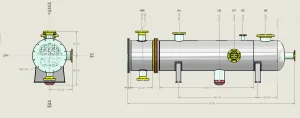
Case Study: Drafting a 3000 PSI Pressure Vessel
To illustrate the drafting process, let’s look at a case study of a 3000 PSI pressure vessel designed for a chemical processing plant.
Design Considerations:
-
Material: SA516 Grade 70 carbon steel
-
Operating Pressure: 3000 PSI
-
Operating Temperature: 200°C
-
Vessel Type: Cylindrical with hemispherical heads
Drafting Process:
-
Initial Layout: Create the basic shell and head dimensions.
-
Nozzle Placement: Add inlet/outlet nozzles, safety valves, and instrumentation connections.
-
Weld Details: Specify weld type, size, and location.
-
Supports: Add skirt supports and lifting lugs with precise dimensions.
-
Annotations: Include ASME-required information like design pressure, temperature, and material specs.
-
Review and Approval: Cross-check the drawing with engineering calculations and perform ASME compliance verification.
Outcome:
The final drawing was fabrication-ready, included all required ASME notations, and minimized potential errors during manufacturing.
Challenges in Drafting for Complex Vessels
Drafting complex pressure vessels involves several challenges:
-
Complex Geometry: Multi-head, multi-nozzle, or high-pressure vessels require precise 3D modeling.
-
Interference with Piping: Drafting must account for surrounding equipment and piping connections.
-
Code Compliance: Meeting ASME or API standards for unusual designs requires attention to detail.
-
Revision Management: Changes in design must be accurately reflected in updated drawings.
-
Collaboration: Coordination between drafters, engineers, and fabricators is critical to prevent costly mistakes.
Overcoming these challenges requires skilled drafters, robust software, and clear communication channels.
Collaboration Between Drafting and Engineering Teams
Effective collaboration is key to producing accurate and efficient pressure vessel drawings.
-
Regular Review Meetings: Ensure that all drawings align with engineering calculations.
-
Version Control: Use software or cloud systems to track revisions.
-
Feedback Loops: Fabricators provide input on manufacturability, which is incorporated into drawings.
-
Interdisciplinary Communication: Drafting teams coordinate with piping, instrumentation, and structural engineers.
This collaborative approach reduces errors, saves time, and ensures that vessels meet both design intent and fabrication feasibility.
Digital Transformation: 3D Modeling in Drafting
The shift from traditional 2D drafting to 3D modeling is transforming pressure vessel design:
-
Enhanced Visualization: 3D models provide a realistic view of complex geometries.
-
Interference Detection: Early identification of clashes between vessel components and surrounding systems.
-
Faster Modifications: Changes in design automatically update all related drawings.
-
Integration with Simulation: 3D models can be used for FEA stress analysis and thermal simulations.
Software like SolidWorks, Autodesk Inventor, and PV Elite 3D allow engineers and drafters to collaborate seamlessly in a digital environment.
Best Practices for Pressure Vessel Drafting
To ensure high-quality, compliant drawings:
-
Follow ASME Standards Strictly: Always cross-check drawings against code requirements.
-
Maintain Clear Layering in CAD: Separate shells, heads, nozzles, welds, and supports for clarity.
-
Use Standard Symbols and Notations: Reduces misinterpretation.
-
Review Before Fabrication: Conduct thorough internal reviews with engineering and fabrication teams.
-
Document Revisions: Keep a detailed revision history for traceability.
-
Leverage 3D Modeling: For complex or high-pressure vessels, 3D modeling reduces errors and improves understanding.
Conclusion
Pressure vessel drafting and drawing is a critical aspect of vessel design, bridging the gap between engineering calculations and real-world fabrication. By adhering to ASME standards, using standardized symbols, leveraging advanced drafting software, and embracing digital transformation through 3D modeling, engineers and drafters can produce accurate, compliant, and fabrication-ready drawings.
Whether you are drafting a simple cylindrical vessel or a complex 3000 PSI pressure vessel, attention to detail, collaboration, and adherence to best practices are the keys to success.