Most vendor pages for plastic analysis software read the same way: a list of capabilities, a few case studies, a request-a-demo button. What they rarely explain is how to actually tell whether one tool’s plastic analysis capability is trustworthy against another’s — which is the question that matters once you’re relying on the result to justify a collapse load, a redistribution factor, or a design that pushes past first yield.
This guide takes a capability- and benchmark-based approach instead. It covers what plastic analysis actually is, when it is genuinely needed, the modeling capabilities and solver methods that separate one tool from another, and how to verify that whichever software you choose is giving you an answer you can stand behind.
What Is Plastic Analysis?
Plastic analysis predicts how a structure behaves once one or more sections exceed their elastic limit and begin to deform permanently, rather than stopping the calculation at first yield the way elastic analysis does.
Elastic Limit, Yielding and Redistribution
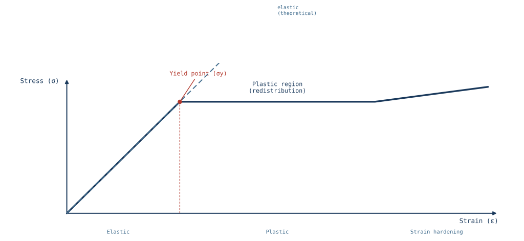
Below the elastic limit, stress and strain are proportional and the structure returns to its original shape when load is removed. Once a section reaches its yield stress, additional load no longer produces a proportional increase in stress at that location — the material yields, and in a statically indeterminate structure, the load that section can no longer carry is redistributed to adjacent, still-elastic parts of the structure. Elastic analysis stops at first yield and treats it as the design limit; plastic analysis continues past that point to capture how much additional capacity the structure has as yielding spreads and load redistributes.
Plastic Hinge vs Distributed Plasticity
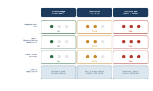
Two distinct modelling philosophies capture this post-yield behaviour. Plastic hinge (or lumped plasticity) models concentrate all inelastic deformation at discrete points — typically member ends or locations of peak moment — while treating the rest of the member as elastic, which mirrors how plasticity actually concentrates in many frame structures. Distributed (spread) plasticity models instead allow yielding to develop gradually along a member’s length and through its cross-section, capturing the transition from partial to full plastification more realistically, at the cost of a heavier computational model. Which one is appropriate depends on the structure and the question being asked, which is the subject of the next section.
When Structural Engineers Need Plastic Analysis Software
Plastic analysis software earns its place when a project genuinely needs to understand behaviour beyond first yield — not by default, and not for every structural check.
Collapse, Limit-State and Pushover Problems
Plastic analysis is the right tool for collapse load determination, limit-state design under codes that permit inelastic redistribution, seismic pushover assessment of ductile structures, and progressive collapse or robustness checks following an accidental loss of a structural element. In each of these cases, the question being asked is explicitly about behaviour after yield — how much reserve capacity exists, where the structure will eventually fail, and by what mechanism — which elastic analysis cannot answer.
Cases Where Linear Analysis Is Still Sufficient
For the majority of everyday structural checks — serviceability, most ultimate limit state design to codes based on elastic section capacities, and any structure expected to remain elastic under its full design load — linear elastic analysis remains the appropriate and more efficient tool. Reaching for plastic analysis software when a linear check would answer the question adds modeling effort, solver complexity, and interpretation risk without a corresponding benefit. Our guide to linear versus nonlinear FEA covers this broader decision in more depth; this article assumes that decision has already been made in favour of plastic behaviour and focuses on the software capability behind it.
Core Modelling Capabilities to Compare
Once plastic analysis is warranted, the software’s modeling capabilities — not its marketing material — determine whether it can represent the actual physics of the problem.
Material Models and Yield Criteria
The material model governs how the software represents post-yield behaviour: elastic-perfectly plastic, bilinear or multilinear hardening, and more advanced models capturing strain-rate sensitivity or cyclic degradation for seismic work. Equally important is the yield criterion applied — von Mises for ductile metals, Tresca in some code-based checks, and Mohr-Coulomb or Drucker-Prager formulations where a concrete or soil-like material is involved. A tool that only offers a single generic yield surface may be adequate for simple steel frame problems but will misrepresent behaviour in mixed-material or geotechnical-structural problems.
Geometric Nonlinearity, Imperfections and Contact
Plastic behaviour rarely occurs in isolation from geometric effects. Large-displacement (P-Delta and P-delta) formulations, the ability to introduce initial geometric imperfections consistent with fabrication tolerances, and contact formulations for connections or bearing surfaces all affect whether a collapse mechanism predicted by the software matches how the structure would actually fail. Software that couples material and geometric nonlinearity within the same solution step, rather than treating them as separate add-on options, generally produces more reliable results for problems where both effects interact — which is the normal case in collapse and pushover analysis.
Solver Methods and Convergence
The solver is where plastic analysis software most clearly separates itself from linear tools, and where an engineer’s judgment about convergence behaviour matters as much as the software’s default settings.
Incremental-Iterative Solution Strategies
Because stiffness changes as yielding progresses, plastic analysis cannot be solved in a single step the way linear analysis can. Load is applied incrementally, and within each increment the solver iterates — typically using a Newton-Raphson or modified Newton-Raphson scheme — until the internal and external forces are in equilibrium within a specified tolerance. The size of the load increment and the tightness of the convergence tolerance both affect accuracy and run time, and neither should be left at a software default without understanding what they mean for the specific problem being solved.
Arc-Length, Stabilization and Failure to Converge
Near a collapse load, a standard load-controlled solver can fail to converge simply because the structure has run out of capacity — the mathematics of the problem, not a modeling error, is what breaks convergence at that point. Arc-length methods trace the equilibrium path through this kind of limit point by controlling a combination of load and displacement rather than load alone, allowing the solver to continue past a peak load and into the post-peak softening region. Artificial stabilization techniques — small amounts of numerical damping — can also help a solver through a difficult increment, but overusing them risks masking a genuine instability rather than resolving a numerical one, which is a distinction worth checking carefully in any convergence report before trusting the result.
Plastic Analysis Methods by Model Fidelity
Plastic analysis software spans a wide range of model fidelity, and the right level depends on the structure and the question, not simply on what the software is capable of at maximum settings.
Frame Plastic-Hinge Models
For frame structures — steel or concrete moment frames, portal frames, braced frames — plastic hinge models at member ends are often sufficient to capture collapse mechanisms and ductility demand with far less computational cost than a full continuum model. This makes them the practical choice for pushover assessment of buildings and for many code-based limit analysis checks, provided the hinge properties (moment-rotation behaviour, interaction with axial load) are defined consistent with the section and material actually being modeled.
Shell and Solid Continuum FEA
Where local stress concentration, connection behaviour, or a genuinely three-dimensional collapse mode governs — plate buckling, complex connections, pressure boundaries, or structures where plasticity does not localize cleanly at member ends — full continuum FEA using shell or solid elements captures behaviour that a lumped plastic hinge model cannot. This comes at substantially higher computational cost and requires closer attention to mesh design, since the local plastic strain result is more mesh-sensitive than a global collapse load typically is. Our broader guide to structural analysis methods covers how continuum FEA fits into the wider structural analysis toolkit.
Verification and Validation Requirements
A plastic analysis result is only as trustworthy as the verification behind it, and this is the step vendor capability lists consistently skip over.
Benchmark Problems and Hand Checks
Before trusting any plastic analysis software on a real project, its collapse load predictions should be checked against problems with a known closed-form or well-established solution — a simple portal frame collapse mechanism solved by hand using virtual work, for instance, or a published benchmark case from the literature. This is not a one-time software qualification exercise; it is worth repeating whenever a new material model, element type, or solver setting is used for the first time, since software behaviour can differ meaningfully between these configurations even within the same package.
Mesh Sensitivity and Energy/Equilibrium Checks
For continuum plastic FEA, a mesh sensitivity study — repeating the analysis with a refined mesh and confirming the result has converged rather than continuing to change — is a minimum requirement before a result is used for design, not an optional refinement. Equilibrium checks (do reaction forces balance applied load, including any load lost to numerical stabilisation) and energy balance checks (is artificial or stabilisation energy a small fraction of total internal energy) are two further checks that catch a result that looks plausible on the surface but is not actually a valid equilibrium solution.
Software Selection Checklist
With the modelling and solver capabilities understood, selecting a specific tool comes down to a shorter set of practical criteria.
Codes, Interoperability and Reporting
Confirm the software’s plastic analysis capability is validated against the design codes actually governing the project — AS 4100, Eurocode 3, or AISC, for instance — and that it produces reporting output (moment-rotation histories, hinge sequence, collapse mechanism plots) in a form that can be independently reviewed and audited, not just a single pass/fail result. Interoperability with the modelling tools already in use on a project reduces the risk of geometry or load errors introduced when transferring a model between packages.
Licensing, Automation, Support and Auditability
Beyond technical capability, licensing structure, the ability to automate repetitive analysis runs (useful for parametric collapse studies or code-compliance sweeps), vendor technical support, and — for regulated or safety-critical work — a clear audit trail showing solver version, settings, and convergence history all factor into a genuine selection decision. A tool that produces excellent results in the hands of an expert user but offers no practical way to document how those results were obtained is a poor fit for work that will eventually need independent review.
Plastic Analysis Capability Matrix
| Capability | Frame Plastic-Hinge Software | Continuum Shell/Solid FEA |
| Typical use case | Building and frame collapse, pushover, ductility demand | Local stress, connections, plates, pressure boundaries |
| Yield/hinge definition | Moment-rotation hinge properties, axial-moment interaction | Full yield criterion (von Mises, Tresca, Drucker-Prager) |
| Geometric nonlinearity | P-Delta, member-level large displacement | Full large-deformation, contact, imperfections |
| Solver demand | Lower — fast enough for iterative design checks | Higher — mesh-dependent, often needs arc-length methods |
| Mesh/discretisation sensitivity | Low — hinge locations are the main modelling decision | High — requires mesh sensitivity study |
| Verification approach | Hand-calculated collapse mechanism, virtual work check | Benchmark FEA cases, energy and equilibrium checks |
Frequently Asked Questions
Which software can perform plastic analysis?
A range of structural analysis and FEA packages support plastic analysis, from frame-analysis programs with plastic hinge capability suited to building collapse and pushover studies, to general-purpose FEA packages offering full continuum plasticity for shell and solid models. The right choice depends on whether the problem is governed by frame-level mechanisms or by local, three-dimensional plastic behaviour.
What is the difference between plastic hinge and nonlinear FEA?
Plastic hinge analysis concentrates inelastic behaviour at discrete points — typically member ends — using moment-rotation relationships, while continuum nonlinear FEA models plasticity as a distributed field across shell or solid elements using a full yield criterion and stress-strain relationship. Plastic hinge models are computationally efficient for frame-level collapse mechanisms; continuum FEA is needed when local, three-dimensional plastic behaviour governs.
How do you verify a plastic analysis model?
A plastic analysis model is verified by checking its predictions against benchmark problems with known solutions, performing a mesh sensitivity study for continuum models, and confirming that equilibrium and energy balance hold in the converged solution, ideally supplemented by an independent hand calculation of the expected collapse mechanism.
Why does a nonlinear plastic analysis fail to converge?
Convergence failure often occurs because the structure has genuinely reached its load-carrying capacity, which a standard load-controlled solver cannot follow past a limit point — this calls for an arc-length or displacement-controlled solution strategy rather than being treated as a modelling error. Convergence can also fail due to overly large load increments, an unstable mesh or element formulation, or contact and boundary conditions that are not well defined.
Conclusion
Choosing plastic analysis software is less about which package has the longest capability list and more about whether its material models, solver strategy, and verification support actually match the problem you need to solve — and whether you can independently demonstrate that the result it produces is correct. A collapse load or ductility demand result that hasn’t been checked against a benchmark, a mesh sensitivity study, or basic equilibrium is not yet a result you can put your name to.
Need an independent review of a nonlinear plastic model or validation of a collapse analysis before it goes into a design submission? Our engineering team supports design verification and advanced simulation work across plastic hinge and continuum FEA models alike. Get in touch to discuss your project.