Structural analysis helps engineers predict how a component or structure will behave under load.
It can calculate stress, strain, deformation, reaction forces, buckling risk, contact pressure, and other important responses.
However, not every structure behaves in a simple or proportional way.
Some structures remain stiff and elastic throughout loading. Others change shape, yield, lose contact, buckle, or develop new load paths.
This difference determines whether engineers should use linear or nonlinear structural analysis.
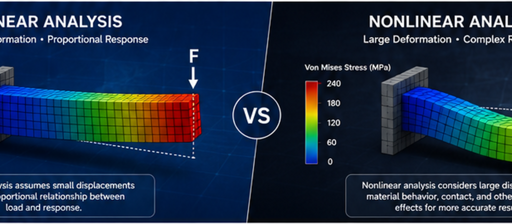
Linear analysis is efficient and suitable for many routine engineering problems. It assumes that the structural response remains proportional to the applied load.
Nonlinear analysis is more advanced. It considers changes in geometry, material behaviour, stiffness, and contact conditions during loading.
Choosing the wrong method can produce misleading results.
A linear model may appear safe while missing plastic collapse, large deformation, instability, or contact separation.
A nonlinear model may also be unnecessary when a simpler analysis can answer the engineering question reliably.
This guide explains the main differences between linear and nonlinear structural analysis. It also provides practical guidance for selecting the right method.
What Is Structural Analysis?
Structural analysis is the process of calculating how a structure responds to loads, supports, connections, and environmental conditions.
The structure may be a building, machine component, pressure vessel, support frame, mining asset, bridge, platform, or industrial assembly.
Engineers use structural analysis to answer questions such as:
- Will the structure support the required load?
- Where will the highest stress occur?
- Will deformation affect operation?
- Could the structure buckle?
- Will a connection remain engaged?
- Could the material yield?
- Is the design compliant with the required standard?
- What modifications could improve performance?
The analysis begins with a representation of the real structure.
This representation includes geometry, material properties, loads, supports, and connections.
Simple structures may be assessed with hand calculations. More complex systems often require Finite Element Analysis, or FEA.
FEA divides the structure into smaller regions called elements. The software then calculates how those elements respond and interact.
The results are only useful when the model represents the physical system correctly.
Engineers must therefore choose suitable assumptions before solving the model.
One of the most important choices is whether the analysis should be linear or nonlinear.
What Is Linear Structural Analysis?
Linear structural analysis assumes that the relationship between load and response remains proportional.
If the applied load doubles, the calculated stress and displacement also double.
If the load is removed, the structure returns to its original condition.
A linear analysis normally assumes:
- Small deformation
- Small rotation
- Linear elastic material behaviour
- Constant structural stiffness
- Unchanging contact conditions
- Unchanging load direction
- No significant structural instability
These assumptions simplify the governing equations.
The solver can usually calculate the structural response in one direct solution. This makes linear analysis fast and efficient.
Linear analysis is widely used for preliminary studies, routine design checks, and structures that remain within the elastic range.
A linear model can still contain complex geometry.
It may include many elements, load cases, materials, and connection types.
The word “linear” does not mean that the structure must be simple. It means that the structural response follows linear assumptions during loading.
Assumptions of Linear Analysis
Engineers should review the main linear assumptions before accepting the results.
Small Deformation
The deformed shape must remain close to the original shape.
The structure may move slightly, but the movement should not change its stiffness or load path significantly.
For example, a stiff steel bracket may deflect by a fraction of a millimetre.
This movement is unlikely to change how the bracket carries the load. A linear solution may therefore be suitable.
However, a thin panel may deflect by several times its thickness.
Its geometry and membrane stiffness may change during loading. This behaviour may require geometric nonlinearity.
Linear Elastic Material Behaviour
The material must remain within its elastic range.
Stress should remain proportional to strain.
The material should also return to its original condition after unloading.
For metals, this generally means that significant yielding should not occur.
When the material enters the plastic range, its stiffness changes. Permanent strain may also develop.
A linear elastic model cannot represent this behaviour accurately.
Constant Boundary Conditions
Supports and connections must remain unchanged during loading.
A bolted interface should not open or slide.
A component should not separate from its support.
A gap should not close as the load increases.
When contact conditions change, the structural stiffness and load path also change. This creates contact nonlinearity.
Constant Load Direction
In a small-deformation model, the load direction is usually based on the original geometry.
This assumption may become inaccurate when the structure rotates significantly.
Pressure loads can also follow a changing surface direction during large deformation.
Stable Structural Response
A linear model assumes that the structure does not experience major instability.
Linear analysis may estimate an elastic buckling factor. However, it cannot fully represent post-buckling behaviour, progressive collapse, or major stiffness changes after instability.
Advantages of Linear Analysis
Linear structural analysis offers several important advantages.
Fast Solution Time
Linear systems usually solve quickly.
This allows engineers to evaluate many load cases and design alternatives efficiently.
Lower Computational Requirements
Linear models generally require less memory and processing power than nonlinear models.
This is useful for large assemblies and preliminary design studies.
Simpler Model Setup
Linear material properties and fixed connections are easier to define.
The model also requires fewer convergence settings.
Clear Result Interpretation
The relationship between load and response is direct.
Engineers can often scale results between proportional load cases.
Useful for Initial Screening
Linear analysis can identify critical regions before a more detailed study begins.
It can also indicate whether nonlinear effects are likely to be important.
Easier Verification
Hand calculations and simplified engineering equations often support linear analysis.
This makes model verification more straightforward.
These advantages make linear analysis an essential engineering tool.
However, speed should never take priority over physical accuracy.
Common Applications of Linear Analysis
Linear analysis is suitable for many routine engineering problems.
Common applications include:
- Elastic stress analysis
- Beam and frame assessment
- Support structure checks
- Bracket analysis
- Equipment foundation loads
- Small-deflection plate analysis
- Pressure loading within elastic limits
- Preliminary design comparisons
- Reaction force calculations
- Load path assessment
- Serviceability checks
- Linear thermal stress analysis
- Modal analysis around an undeformed state
For example, a steel equipment platform may remain elastic under normal operating loads.
Its deflection may also remain small compared with its overall dimensions.
A linear static model can provide useful stress and displacement results.
A pressure vessel may also be assessed using linear elastic analysis when deformation remains small and code-based stress classification is required.
The engineer must still review local stress concentrations, mesh quality, boundary conditions, and acceptance criteria.
What Is Nonlinear Structural Analysis?
Nonlinear structural analysis accounts for changes that occur as the load is applied.
The relationship between load and response is no longer proportional.
Doubling the load may more than double the displacement.
The additional load may also cause yielding, contact separation, buckling, or a major change in structural stiffness.
A nonlinear solver normally applies the load in increments.
At each increment, the solver updates the model and checks whether equilibrium has been reached.
The solver may require several iterations before moving to the next increment.
This process continues until the complete load is applied or the structure can no longer achieve a stable response.
Nonlinear analysis can represent behaviour that a linear model cannot capture.
Examples include:
- Plastic deformation
- Large rotation
- Large displacement
- Changing contact
- Friction
- Gaps
- Material damage
- Rubber behaviour
- Creep
- Hyperelasticity
- Post-buckling response
- Progressive collapse
Nonlinear analysis can provide a more realistic result.
However, it requires more data, greater computational resources, and more engineering judgement.
Why Nonlinear Behaviour Occurs
Nonlinear behaviour occurs when the structure changes during loading.
The change may affect stiffness, geometry, restraints, or material response.
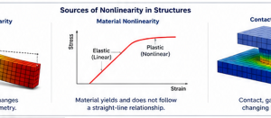
Engineers normally divide structural nonlinearity into three main categories:
- Geometric nonlinearity
- Material nonlinearity
- Contact or boundary nonlinearity
A single model may contain one, two, or all three types.
For example, a bolted steel assembly may experience contact separation, local yielding, and large rotation.
The engineer must identify which nonlinear effects influence the final decision.
Adding every possible nonlinear feature is not always necessary.
The model should include the behaviours that materially affect the engineering result.
Geometric Nonlinearity
Geometric nonlinearity occurs when deformation changes the structural response.
The structure may experience large displacement, large rotation, or stiffness changes caused by its deformed shape.
Common examples include:
- Cables
- Membranes
- Thin panels
- Slender columns
- Flexible frames
- Snap-through structures
- Large-deflection plates
- Buckling shells
- Flexible lifting components
A cable has very little bending stiffness.
Its ability to carry transverse load depends on tension and changing geometry.
A small-deformation linear model cannot represent this behaviour correctly.
Thin plates can also develop membrane action after significant deflection.
This membrane action may increase stiffness.
In other situations, compression may reduce stiffness and lead to buckling.
Geometric nonlinearity is also important when the load direction changes with deformation.
Pressure acting on a flexible surface is a common example.
The pressure remains normal to the changing surface. A nonlinear formulation updates this direction as the structure moves.
Material Nonlinearity
Material nonlinearity occurs when stress is no longer proportional to strain.
The material stiffness may change with load, temperature, time, or loading history.
Plasticity is one of the most common forms of material nonlinearity.
When metal reaches its yield point, permanent strain begins to develop.
The tangent stiffness then differs from the original elastic stiffness.
A plastic material model can represent this change.
It can also predict:
- Yielded regions
- Permanent deformation
- Load redistribution
- Plastic collapse
- Residual strain
- Strain localisation
Other forms of material nonlinearity include:
- Hyperelastic rubber behaviour
- Creep
- Viscoelasticity
- Concrete cracking
- Concrete crushing
- Soil plasticity
- Composite damage
- Foam compression
- Temperature-dependent material behaviour
The required material data depends on the engineering problem.
A basic elastic-plastic steel model may require a complete stress-strain curve.
A cyclic model may require kinematic hardening data.
A creep model may require time-dependent and temperature-dependent parameters.
Using incomplete or unsuitable material data can significantly reduce the reliability of a nonlinear analysis.
Contact Nonlinearity
Contact nonlinearity occurs when structural interfaces change during loading.
Two surfaces may:
- Touch
- Separate
- Slide
- Stick
- Transfer friction
- Close a gap
- Lose contact
- Change contact area
These changes alter structural stiffness and the load path.
Common contact applications include:
- Bolted joints
- Bearings
- Gears
- Press fits
- Flanged connections
- Seals
- Mechanical stops
- Pin connections
- Lifting assemblies
- Equipment foundations
- Component-to-component interfaces
A linear model may use a bonded connection between surfaces.
This approach forces the surfaces to remain attached.
It may be suitable for representing a continuous weld. However, it can be unrealistic for an unbonded bolted interface.
A nonlinear contact model can determine where the joint remains compressed and where it opens.
It can also estimate sliding, friction force, and local contact pressure.
Contact models are often more difficult to solve.
The solver must continuously update which surfaces are active.
Careful contact settings and suitable mesh refinement are therefore important.
Linear vs Nonlinear Structural Analysis: Key Differences
Linear and nonlinear methods differ in assumptions, solution process, accuracy, and engineering effort.
| Comparison Area | Linear Structural Analysis | Nonlinear Structural Analysis |
|---|---|---|
| Load-response relationship | Proportional | Non-proportional |
| Deformation assumption | Small deformation | Small or large deformation |
| Material response | Linear elastic | Elastic-plastic or another nonlinear model |
| Contact behaviour | Fixed and unchanged | Can open, close, slide, or separate |
| Structural stiffness | Constant | Updated during loading |
| Solution method | Usually one direct solution | Incremental and iterative |
| Computational demand | Lower | Higher |
| Convergence difficulty | Usually limited | Can be significant |
| Permanent deformation | Not represented | Can be represented |
| Collapse behaviour | Limited | Can be assessed |
| Typical use | Routine elastic assessment | Complex or extreme structural behaviour |
Differences in Assumptions
Linear analysis relies on simplifying assumptions.
These assumptions make the model efficient. However, they also limit the behaviour that the model can represent.
Nonlinear analysis relaxes one or more of these assumptions.
It updates the model as loading progresses.
The important question is not which method is more advanced.
The correct question is which assumptions match the real behaviour of the structure.
Differences in Accuracy
Nonlinear analysis is not automatically more accurate.
A nonlinear model with poor material data can be less reliable than a verified linear model.
Accuracy depends on:
- Geometry
- Mesh quality
- Material properties
- Contact definitions
- Boundary conditions
- Applied loads
- Solver controls
- Validation
- Engineering interpretation
Linear analysis is accurate when its assumptions remain valid.
Nonlinear analysis becomes necessary when nonlinear effects materially change the answer.
Computational Requirements
Linear models normally require less computing time.
The stiffness matrix may be assembled and solved once for each load case.
Nonlinear models update stiffness during loading.
They may require many load increments and equilibrium iterations.
Computational demand increases further when the model includes:
- Complex contact
- Friction
- Large deformation
- Plasticity
- Material damage
- Instability
- Transient loading
- A very fine mesh
- Many interacting components
Convergence difficulty can also increase project time.
A model may require changes to the load step, contact settings, damping, stabilisation, or mesh.
Engineering Complexity
Nonlinear analysis requires more engineering decisions.
The analyst may need to define:
- Load steps
- Increment sizes
- Material curves
- Contact behaviour
- Friction coefficients
- Large-deformation settings
- Convergence tolerances
- Failure criteria
- Output controls
The analyst must also interpret solver warnings.
A failure to converge does not always mean that the real structure has failed.
It may result from poor contact settings, unsuitable increments, or mesh problems.
However, convergence loss can also indicate physical instability or collapse.
Engineering judgement is needed to distinguish between numerical and physical causes.
When Should You Use Linear Analysis?
Linear analysis is suitable when the model remains close to its original state.
The following conditions support a linear approach:
- Deformation is small
- Rotation is small
- Material remains elastic
- Contact conditions do not change
- Supports remain valid
- Load direction remains approximately constant
- Buckling or collapse is not the main concern
A linear model is often the best starting point.
It provides fast insight into the load path and critical regions.
The results can also indicate whether a nonlinear study is required.
Small Deformation Problems
Use linear analysis when displacement remains small compared with the structural dimensions.
A stiff bracket, frame, baseplate, or support often meets this condition.
The analyst should compare deformation with thickness, span, clearance, and connection geometry.
There is no universal deformation percentage that applies to every structure.
The key question is whether deformation changes stiffness, equilibrium, or the load path.
Preliminary Design Studies
Linear analysis is valuable during early design.
Engineers can compare several concepts quickly.
They can evaluate:
- Material options
- Member sizes
- Thickness changes
- Support locations
- Reinforcement layouts
- Load paths
- Alternative designs
The model can identify weak concepts before detailed nonlinear work begins.
Routine Structural Assessments
Many routine assessments remain within the elastic range.
Examples include service load checks, deflection reviews, reaction calculations, and code-based elastic stress evaluations.
Linear analysis is also useful when the design requirement specifically assumes elastic behaviour.
However, the analyst must still check whether local nonlinear effects could govern the result.
When Should You Use Nonlinear Analysis?
Use nonlinear analysis when changes during loading affect the structural response.
Warning signs include:
- Large displacement
- Large rotation
- Yielding
- Permanent deformation
- Contact opening
- Sliding
- Gap closure
- Buckling
- Post-buckling behaviour
- Flexible materials
- Load redistribution
- Progressive failure
The need for nonlinearity should come from physical behaviour, not software preference.
Large Deformation Structures
Large-deformation analysis is required when movement changes structural stiffness or load direction.
Examples include cables, membranes, thin shells, flexible lifting systems, and highly deformable components.
The model should update the geometry throughout the loading process.
Plastic Material Behaviour
Material nonlinearity is required when yielding affects performance.
This is common in:
- Overload assessment
- Collapse analysis
- Crash simulation
- Forming processes
- Seismic ductility
- Local plasticity
- Residual deformation studies
- Limit-load assessment
The material curve should represent the correct temperature, loading direction, and strain range where possible.
Contact and Assembly Simulations
Nonlinear contact is needed when interfaces can change.
Bolted joints, pins, bearings, gears, clamps, and press fits often require contact modelling.
The analysis may assess:
- Separation
- Sliding
- Friction
- Contact pressure
- Bolt load transfer
- Joint stiffness
- Local bearing stress
A simplified linear model may still be useful for initial screening.
However, it may not capture the final load distribution accurately.
Failure and Collapse Assessment
Nonlinear analysis is often required when the objective is to predict failure.
Linear stress contours cannot fully represent:
- Plastic collapse
- Post-buckling strength
- Progressive contact loss
- Material damage
- Large deformation
- Load redistribution
Collapse assessment should include clear acceptance criteria.
The engineer must also distinguish between local yielding and global failure.
A small yielded region does not always mean that the entire structure has lost its capacity.
Risks of Using Linear Analysis for Nonlinear Problems
Using linear analysis outside its valid range can create several engineering risks.
Underestimating Deformation
The model may retain too much stiffness.
As a result, it may predict smaller displacement than the real structure.
Missing Plastic Redistribution
A linear model may report a high local stress.
However, it cannot show how yielding redistributes load.
In some cases, this makes the result unnecessarily conservative.
In other cases, the model may miss progressive plastic collapse.
Missing Contact Separation
A bonded or fixed connection may transfer tension that the real interface cannot carry.
This can create a false load path.
Missing Sliding and Friction
Real assemblies may move under load.
A linear bonded model cannot predict slip or frictional resistance.
Missing Buckling Behaviour
Linear elastic buckling analysis estimates an ideal critical factor.
It does not represent imperfections, material yielding, or post-buckling response.
Incorrect Load Direction
Large rotation can change how pressure, gravity, or follower loads act.
A small-deformation model may retain the original load direction.
False Safety Conclusions
The most serious risk is a safe-looking result based on invalid assumptions.
Model simplicity must never hide the governing failure mechanism.
Real-World Engineering Examples
Pressure Vessel Analysis
Linear elastic analysis is widely used for pressure vessel stress evaluation.
It can calculate membrane, bending, and local stresses under pressure and external loads.
This approach is often suitable when deformation is small and material response remains elastic.
Nonlinear analysis may be required for:
- Plastic collapse
- Nozzle interaction
- Gasket contact
- Flange separation
- Large local deformation
- Buckling
- External pressure
- Limit-load assessment
- Severe thermal loading
For example, a nozzle region may experience local yielding.
A nonlinear model can show whether this yielding remains limited or develops into structural collapse.
Mining Equipment
Mining equipment experiences heavy loading, vibration, impact, wear, and changing contact conditions.
Linear analysis can support the preliminary assessment of frames, supports, chutes, and machine structures.
Nonlinear analysis may be required for:
- Bucket contact
- Impact loading
- Bolted joint behaviour
- Large boom movement
- Plastic overload
- Rubber liners
- Crushing contact
- Local buckling
- Failure replication
The operating load should represent the real equipment duty.
Site measurements can improve both linear and nonlinear models.
Heavy Industrial Structures
Heavy industrial structures include platforms, transfer towers, support frames, furnaces, conveyors, and processing equipment.
Linear analysis is suitable for many normal operating load cases.
Nonlinear analysis may be required when the structure contains:
- Slender compression members
- Large thermal movement
- Sliding supports
- Contact restraints
- Flexible connections
- Severe overload
- Progressive collapse risk
- Material yielding
The selected analysis method may also change between load cases.
A structure can use linear analysis for service loads and nonlinear analysis for an extreme event.
Decision Guide: Linear or Nonlinear Analysis?
Use the following process before selecting the analysis method.
Step 1: Define the Engineering Question
Determine what the analysis must prove.
Is the objective to calculate elastic stress, service deflection, permanent deformation, collapse load, or contact pressure?
Step 2: Review Expected Deformation
Determine whether displacement or rotation could change the geometry or load path.
Step 3: Review Material Stress and Strain
Check whether local or global yielding is expected.
Do not rely only on nominal stress.
Step 4: Review Structural Interfaces
Identify gaps, friction, separation, sliding, bolts, pins, bearings, and other contacts.
Step 5: Review Stability
Determine whether buckling, snap-through, or post-buckling behaviour could control the design.
Step 6: Start With the Simplest Valid Model
Use linear analysis when its assumptions are justified.
Move to nonlinear analysis when a nonlinear effect could change the engineering decision.
Step 7: Validate the Results
Compare the results with hand calculations, code equations, measurements, physical tests, or benchmark models.
Step 8: Document the Decision
The final report should explain why the selected method is suitable.
This helps reviewers understand both the strengths and limitations of the model.
Frequently Asked Questions
What is the main difference between linear and nonlinear structural analysis?
Linear analysis assumes proportional structural response and constant stiffness.
Nonlinear analysis updates the model as geometry, materials, or contact conditions change.
Is nonlinear analysis always more accurate?
No.
It is more suitable for nonlinear behaviour, but accuracy still depends on model inputs, assumptions, and validation.
Can linear analysis include complex geometry?
Yes.
A geometrically complex model can still use linear material and small-deformation assumptions.
Does stress above yield always require nonlinear analysis?
If yielding affects the engineering conclusion, material nonlinearity is normally required.
A local singular stress peak should first be interpreted carefully.
Is contact always nonlinear?
Changing contact is nonlinear.
However, a permanently bonded interface can often be represented using a linear connection.
When is large-deformation analysis required?
It is required when movement changes stiffness, equilibrium, load direction, or contact conditions.
Can linear analysis predict buckling?
Linear eigenvalue buckling can estimate an ideal buckling factor.
Nonlinear analysis is usually required to study imperfections, plasticity, and post-buckling behaviour.
Why do nonlinear models fail to converge?
Possible causes include poor contact settings, large load increments, instability, an inadequate mesh, or unrealistic material data.
Convergence loss may be numerical or physical.
Should every project begin with nonlinear analysis?
No.
A verified linear model is often the most efficient starting point.
Nonlinear complexity should be added only when the physical problem requires it.
Conclusion
Linear and nonlinear structural analysis serve different engineering purposes.
Linear analysis is fast, efficient, and reliable when deformation remains small, materials remain elastic, and connection conditions do not change.
Nonlinear analysis is required when geometry, material response, or contact conditions change during loading.
The correct choice depends on the physical behaviour of the structure.
It should not depend only on software availability or model complexity.
Engineers should begin with a clearly defined engineering question.
They should then review deformation, yielding, contact, stability, and possible failure modes.
A linear model may be sufficient for routine structural checks and preliminary design.
A nonlinear model may be essential for large deformation, plastic collapse, contact interaction, instability, or failure assessment.
The best analysis is not the most complicated model.
It is the simplest model that represents the governing behaviour and supports a reliable engineering decision.