Type “strongest bridge design” into a search bar and most results hand you a single winner, usually the truss, sometimes the arch, and move on. That answer is comfortable but incomplete. A 400-meter river crossing and a 12-meter farm-access bridge are not competing for the same title, and a system that is unbeatable on one site can be the wrong choice on the next. This article treats strength as a set of engineering criteria rather than a trophy, walks through how beam, truss, arch and suspension bridges actually carry load, and ends with a decision matrix you can apply to a real span instead of a slogan.
What Does ‘Strongest’ Mean in Bridge Design?
Before comparing systems, it helps to agree on what the question is actually asking. In everyday language, “strong” means a bridge that will not break. In structural engineering, that single word hides at least four separate properties, and a design can score well on one and poorly on another.
Strength vs Stiffness, Stability and Serviceability
Strength, in the narrow sense, is the maximum load a member can carry before it yields or fractures. Stiffness is different: it is resistance to deformation, and a member can be strong enough not to break yet still deflect more than a bridge deck can tolerate. Stability covers buckling and overturning, failure modes that have nothing to do with material strength and everything to do with geometry. Serviceability is the quieter constraint that governs daily use, things like vibration, deck cracking and long-term deflection under repeated traffic. A bridge that is optimized for raw load capacity but ignores stiffness or stability is not a stronger bridge, it is an incomplete one.
Why Span and Load Case Change the Answer
The second reason a single “strongest” answer fails is span. Every bridge type has a span range where its geometry is efficient and a range where it becomes wasteful or structurally unworkable. A truss that performs beautifully at 60 meters is not a candidate at 1,000 meters, and a suspension system that is unrivaled at 1,000 meters is needlessly expensive at 20 meters. Load case matters just as much: a pedestrian footbridge, a heavy rail crossing and a hurricane-exposed coastal viaduct are not solving the same problem, even if the span length happens to match. Strength has to be judged against the specific span, site and load combination a project actually faces.
How Loads Travel Through the Main Bridge Types
Every bridge, regardless of type, has one job: get the forces from where they are applied to the ground, safely and predictably. The differences between beam, truss, arch and suspension bridges come down to the path that force takes to get there.
Dead, Live, Wind and Seismic Loads
Dead load is the weight of the structure itself, permanent and predictable. Live load is traffic, pedestrians and anything that moves across the deck, variable in magnitude and position. Wind load acts laterally and, on long or flexible spans, can also excite oscillation. Seismic load introduces sudden, reversing accelerations that test a structure’s ductility rather than just its static capacity. A design that handles dead and live load well can still fail under wind or seismic demand if its load path was not built with those cases in mind, which is exactly why “strongest” cannot be judged from gravity loading alone.
Load Paths, Redundancy and Progressive Collapse
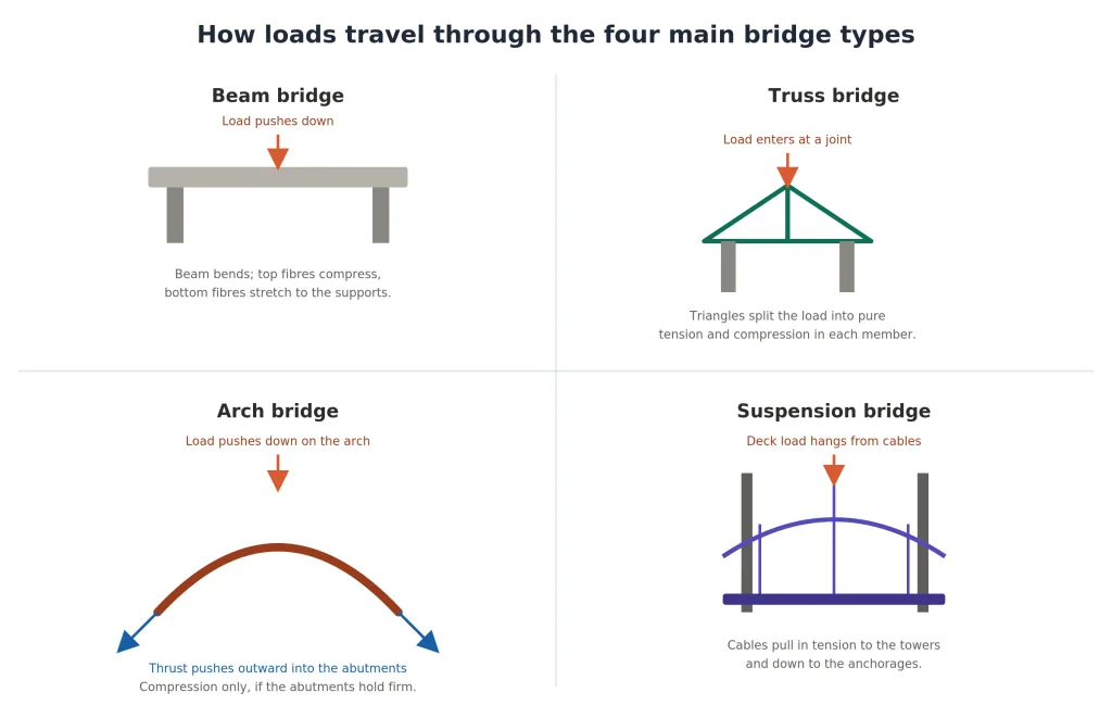
A load path is the sequence of members and connections that carries force from the deck to the foundations. Some systems have many parallel paths, so the loss of one member redistributes force rather than triggering collapse; this is redundancy. Others rely on a small number of critical members or connections, where a single failure can cascade into the kind of progressive collapse investigators look for after a bridge failure. Redundancy is not a cosmetic feature, it is one of the clearest technical definitions of “strong” a bridge can have, and it varies enormously between the four systems compared here. Tracing these paths in detail is the core purpose of structural analysis, which is what converts a load-path diagram into verified member sizes.
Alt text: Diagram showing how load travels through a beam, truss, arch and suspension bridge, with arrows marking bending, triangulated tension and compression, arch thrust into abutments, and cable tension to towers.
Beam Bridges: Where Simplicity Is Strongest
A beam bridge is the most basic structural form: a horizontal member spanning between two supports, carrying load through bending. The top of the beam compresses, the bottom stretches, and the whole system relies on the beam’s own flexural stiffness rather than any clever geometry.
Best-Fit Span and Construction Conditions
Beam bridges are strongest, in the practical sense, where the span is short and the construction schedule is tight. Precast concrete or rolled steel beams can be fabricated off-site and lifted into place quickly, which makes this type the default for highway overpasses, culverts and short rural crossings. The simplicity that limits its span range is also what makes it fast, inspectable and cheap to maintain, which is a legitimate form of engineering strength even though it rarely wins a headline comparison.
Common Capacity and Deflection Limits
The limiting factor for a beam bridge is almost always deflection and bending capacity, not raw material strength. As span increases, the required beam depth grows faster than the useful load it can carry, which is why simple beam spans in steel or concrete typically top out in the 30 to 50 metre range before box-girder or truss reinforcement becomes more economical. Past that point, a beam bridge is not unsafe, it is simply outcompeted by systems that use less material to do the same job.
Truss Bridges: Efficient Strength Through Triangulation
A truss bridge replaces the solid beam with a framework of straight members arranged in triangles. Because a triangle is the only polygon that cannot change shape without changing the length of its sides, every member in a well-designed truss carries pure axial force, either tension or compression, with almost no bending. That is the source of the truss’s famous strength-to-weight ratio.
Pratt, Howe and Warren Truss Behaviour
The three classic configurations differ mainly in how they orient diagonal members. A Pratt truss puts diagonals in tension under typical gravity load, which suits steel well since steel handles tension efficiently. A Howe truss reverses this, putting diagonals in compression, historically useful when timber, which resists compression better than tension, was the primary material. A Warren truss uses equilateral triangles without verticals, giving a repetitive, materially efficient pattern that is common on modern pedestrian and rail bridges. None of these is universally “the strongest” configuration; each matches a different material and load pattern.
Compression Buckling, Connections and Fatigue
The truss’s efficiency comes with specific failure modes that a beam does not have to worry about. Compression members can buckle sideways well before they reach their material yield strength, so their unsupported length has to be controlled just as carefully as their cross-section. Buckling is a nonlinear structural behaviour, which is why it cannot be captured by a simple linear stress check alone. Every joint is a connection design problem in its own right, since a truss is only as strong as its weakest gusset plate or pin. Repeated live load also raises fatigue concerns at these connections over the structure’s service life. A truss bridge is not simply “strong,” it is strong on the condition that buckling, connections and fatigue are each detailed correctly.
Arch Bridges: Using Compression to Advantage
An arch bridge carries load almost entirely in compression, curving the primary structural line so that vertical load is converted into a force that pushes outward and down along the arch toward the supports. Materials that are excellent in compression but weak in tension, historically stone and unreinforced masonry, and today often concrete, are a natural fit.
Thrust, Abutments and Foundation Demand
The defining engineering challenge of an arch is thrust, the outward horizontal force generated at each end of the curve. Unlike a beam or truss, an arch cannot simply be set down on any foundation; it needs abutments or a tied bottom chord capable of resisting that outward push without spreading. This is why arches are strongly associated with rock canyons and firm ground, sites where the foundation can absorb thrust economically, and why they become expensive on soft soil where restraining that force requires substantial additional foundation work.
When an Arch Outperforms a Truss
An arch tends to outperform a truss when the span is long enough that a truss’s self-weight starts working against it, and when the site offers strong abutment conditions, such as a gorge, valley or firm rock face. In those conditions, an arch can achieve a longer clear span with less material than an equivalent truss, because compression allows more efficient use of high-strength materials than the mixed tension-compression demand a truss places on every member. Where the ground is soft or the crossing is over open water with no natural abutment, a truss, beam or suspension system usually wins on cost and construction feasibility instead.
Suspension and Cable-Stayed Bridges for Long Spans
When the span grows beyond what any rigid superstructure can economically achieve, cables take over. Suspension bridges hang the deck from two main cables draped between towers, while cable-stayed bridges run cables directly from the towers to the deck in a fan or harp pattern. Both convert vertical deck load into tension, which steel cable carries with extraordinary efficiency relative to its weight. Crossings at this scale sit firmly within major infrastructure programes, where the structural risk and the construction budget both scale with span length.
Cable Load Paths and Aerodynamic Stability
In a suspension bridge, deck load transfers through vertical hangers into the main cable, which carries it in tension to the towers and finally into massive anchorages at each end. In a cable-stayed bridge, the deck-to-cable-to-tower path is more direct, without the need for separate ground anchorages, which simplifies the foundation problem but changes how the deck itself has to resist compression from the cable angles. Long, flexible decks of both types are vulnerable to wind-induced oscillation, so aerodynamic shaping of the deck cross-section and damping systems are not optional extras, they are part of what makes the structure strong enough to survive its service life.
Anchorages, Towers and Construction Complexity
The strength of a suspension bridge is inseparable from its anchorages, the enormous concrete or rock-anchored blocks that resist the pull of the main cables. Towers must be tall and stiff enough to carry the vertical load down to their own foundations while resisting the horizontal components introduced by the cable geometry. Construction sequencing, spinning or lifting cables, erecting towers in stages, and closing the deck at midspan, is itself a structural engineering problem, which is one reason these bridges carry a construction cost and schedule that only becomes justified once the span is genuinely too long for anything else.
Which Bridge Type Is Strongest for Your Project?
Given everything above, the honest answer to “what is the strongest bridge design” is: it depends on span, site conditions, load case, material availability and budget, and a competent selection process weighs all five before a system is chosen.
Decision Matrix by Span, Site and Material
| Factor | Beam | Truss | Arch | Suspension / cable-stayed |
| Typical span range | Up to ~50 m | ~50–300 m | ~50–500 m (site-dependent) | 300 m to over 2,000 m |
| Best foundation condition | Any firm support | Any firm support | Strong abutments, rock or valley walls | Deep, stable anchorage sites |
| Strength-to-weight ratio | Moderate | High | High in compression | Very high in tension |
| Redundancy | Low to moderate | Moderate to high (parallel members) | Low (thrust-dependent) | Low to moderate (multiple cables help) |
| Sensitivity to wind/seismic | Low | Moderate | Moderate | High, needs specific mitigation |
| Relative construction speed | Fast | Moderate | Slower, formwork-heavy | Slowest, most complex |
| Relative cost per span | Lowest | Low to moderate | Moderate to high | Highest |
Worked Selection Scenarios and Final Answer
A 25-meters farm-access crossing over a shallow creek, with no unusual load or site constraint, is a beam bridge every time; anything more elaborate would be over-engineering. A 150-meters highway crossing over a river with firm banks and moderate live load is squarely truss territory, where triangulated steel gives the best balance of span, weight and cost. A 200-meters crossing through a steep, rocky gorge with strong natural abutments favors an arch, since the site itself absorbs thrust efficiently and the compression-dominated load path suits the terrain. A kilometer-scale crossing over open, deep water with no intermediate support possible leaves only a suspension or cable-stayed system as a structurally viable option, whatever the cost.
So the short, conditional answer is this: the truss offers the best general-purpose strength-to-weight ratio across a wide range of mid-length spans, the arch is strongest when the site provides compression-friendly abutments, and the suspension bridge is strongest, in fact the only workable option, once span length outgrows every rigid alternative. Numerical analysis against the governing load combinations and design code, confirmed through independent design verification, not a general ranking, is what ultimately confirms which of these is strong enough for a specific project.
FAQ
What is the strongest type of bridge? There is no single strongest type in absolute terms. Truss bridges usually have the best strength-to-weight ratio for short to medium spans, arch bridges are strongest where the site provides firm compression abutments, and suspension or cable-stayed bridges are the only structurally viable option for the longest spans. The right answer depends on span, site and load case.
Is a truss bridge stronger than an arch bridge? For the same span and site, a truss is generally more material-efficient on softer ground or where no natural abutment exists, since it does not depend on outward thrust. An arch can be more efficient on the same span if the site offers strong natural abutments, because compression allows better use of high-strength materials. Neither is universally stronger; the site conditions usually decide it.
Which bridge design carries the most weight? In absolute terms, modern long-span suspension and cable-stayed bridges carry the greatest total load because they are built at the scale required for the heaviest traffic volumes and longest crossings. Per unit of material used, well-detailed truss and arch designs are typically more efficient at moderate spans.
Why are triangles used in strong bridges? A triangle is geometrically stable: its shape cannot change unless the length of one of its sides changes. This forces every member of a triangulated truss to carry load as pure axial tension or compression rather than bending, which uses material far more efficiently than a solid beam and is the underlying reason truss bridges achieve such a high strength-to-weight ratio.
Choosing between these systems on a real project means running the numbers against actual site data, code-mandated load combinations and construction constraints, not matching a span length to a rule of thumb. If your project needs that level of concept-stage structural evaluation and engineering design before committing to a bridge type, our team can run the comparative structural analysis for your specific span and site. Once a bridge type is selected, our guide to bridge design software covers the modeling tools used to take that concept into detailed design.