Insulation is usually the last item specified on a reactor pressure vessel and the last one inspected. Yet it decides the surface temperature people can touch, the heat the process loses, and, less obviously, whether the shell underneath corrodes unseen for years. A material data sheet alone cannot answer any of those questions.
This guide treats insulation as a system: the insulating material, the jacket, the supports, the details at nozzles and closures, the drainage, and the access needed to inspect what lies underneath. It is written for process, mechanical, integrity and insulation engineers and plant owners working with high temperature vessels in oil and gas, industrial chemicals and similar plants. It covers process reactors only. Shell thickness, pressure rating and overall vessel design are covered in our guides to reactor pressure vessel design and pressure vessel design, and nuclear reactor vessels have their own insulation qualification regime.
Three ideas run through the article. Thermal performance is decided at the details, not by the average thickness. The jacket, not the insulation, is the weather barrier. And an insulation system you cannot inspect is a liability. For the wider context, see our high temperature pressure vessels industry page.
Why Insulate a Reactor Pressure Vessel?
Insulation serves several purposes at once, and they can pull in different directions. Write them down before choosing anything.
Heat Loss, Personnel Protection and Process Stability
- Heat loss: limits wasted energy and the duty on heaters or on the reaction itself. Thickness is normally an economic trade-off.
- Process stability: keeps the wall above condensation, freezing and dew points, shortens heat-up, and avoids cold spots where material deposits or acid condenses. For exothermic reactors it also slows cooling in a loss-of-cooling event, so check the hazard study.
- Personnel protection: keeps accessible surfaces below a touch temperature. Many owners specify around 60 °C, but the right limit depends on surface material, contact time and the owner’s standard; ASTM C1055 and ISO 13732-1 describe burn thresholds. Where insulation is impractical, guards do the same job.
Safety Functions and Inspection Constraints
Insulation can also support safety. Some fire relief-sizing methods allow a credit for insulation, but only if it stays in place and performs in a fire and under a hose stream, so that must be verified, not assumed. Every benefit carries a cost. Insulation hides the shell from view, and porous materials can soak up leaked flammable fluids and ignite at temperatures below the fluid’s normal autoignition point. Design the safety functions and the inspection strategy together.
Thermal Design Inputs
Poor inputs give a confident answer to the wrong question. Gather these before sizing anything.
Operating/Design Temperatures and Transients
Select insulation for the hot-face temperature the system will actually see, including upsets, steam-out and regeneration, not just normal operation. Then add the transients: start-up and shutdown rates, cycling frequency and hold periods. Cycling matters twice. It moves the shell relative to the jacket, which opens gaps, and it drives the wet–dry cycles that promote corrosion under insulation. Even vessels that run hot most of the time spend long periods in the corrosion-prone temperature band during start-up and shutdown, and in cooler regions such as skirts, nozzles and top heads.
Ambient Conditions, Emissivity and Allowable Heat Loss
Use different ambient cases for different checks: hot, still and sunny for surface temperature; cold and windy for heat loss and dew point. Jacket emissivity matters more than many expect. Bright aluminium radiates poorly, so the same insulation gives a warmer outer surface than a painted or weathered jacket. ASTM C680 and ISO 12241 give calculation rules.
| Input | Why it matters | Common mistake |
| Hot-face temperature (normal, upset, steam-out) | Sets material limits and layer arrangement | Using normal operation only |
| Cycling and start-up rate | Drives expansion movement and wet–dry cycles | Ignoring intermittent service |
| Ambient, wind and solar gain | Different worst cases for heat loss and surface temperature | One ambient case for both |
| Jacket emissivity | Changes outer surface temperature and heat loss | Assuming a generic value |
| Allowable heat loss or surface target | Defines what “adequate” means | Not agreeing the criterion up front |
| Environment (marine, chemical, washdown, foot traffic) | Governs jacket type and sealing | Treating the jacket as cosmetic |
Insulation Materials and System Architecture
Fibrous, Cellular and Microporous Materials
No single family wins on every criterion. Temperature limits and conductivity vary by product and mean temperature, so confirm both against manufacturer data.
| Family | Strengths | Watch-outs |
| Fibrous (mineral wool, glass fibre, ceramic fibre) | Wide temperature range, conforms to shapes, economical | Absorbs and retains water; conductivity rises sharply when wet; can wick leaked fluids; compresses under load |
| Cellular (cellular glass, calcium silicate, perlite) | Rigid and load-bearing; cellular glass is closed-cell and water resistant | Brittle, needs expansion joints; calcium silicate and perlite absorb water |
| Microporous and aerogel | Lowest conductivity, so thin sections at nozzles, tight clearances and weight-limited areas | Higher cost, dust and handling; verify hydrophobic treatment and long-term wet performance |
For austenitic stainless steel, specify insulation with controlled leachable chlorides; ASTM C795 is the usual reference. For vessels with an internal refractory lining the shell runs cooler and the external problem changes; our refractory design guide covers the lining side.
Layers, Jacketing, Supports and Penetrations
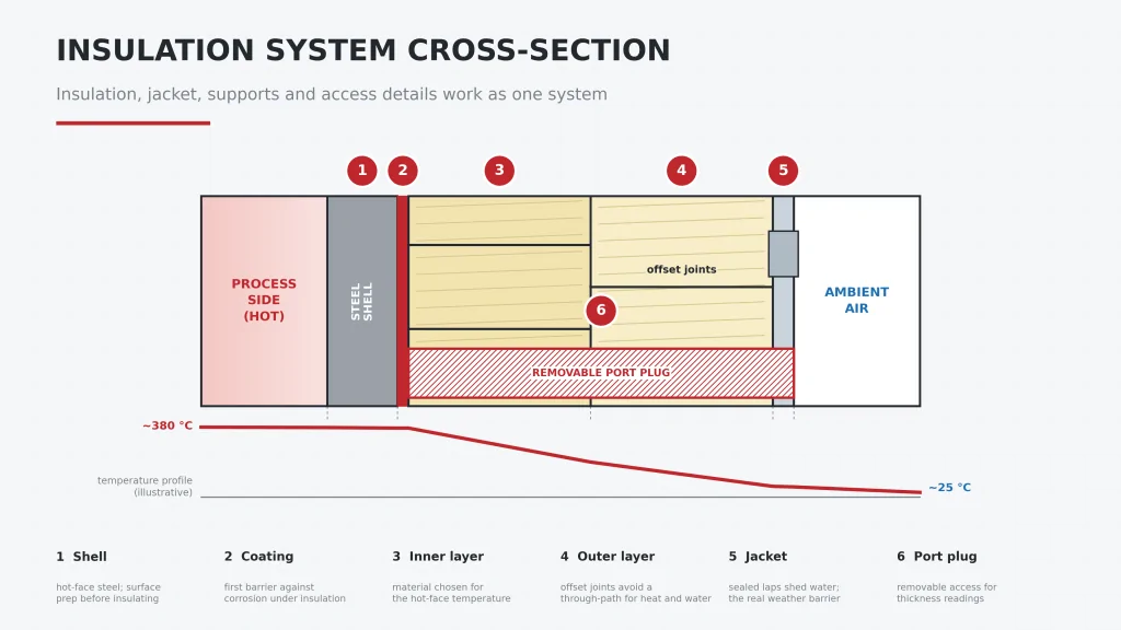
The cross-section at the top of this article shows how the parts work together.
- Layers: use two or more layers with offset joints, so no joint runs straight from shell to jacket. Put the highest-temperature material on the hot face.
- Jacket: sealed laps that shed water, on sloped tops, form the weather barrier. Aluminium is common; stainless steel is preferred where a fire could melt aluminium.
- Supports: use support rings on standoffs, not welded directly to the shell, so water and heat have no easy path.
- Penetrations: flash and seal every nozzle, instrument connection, ladder clip and lug, and give each a documented detail.
Thermal Bridges and Critical Details
A uniform blanket of insulation gives the calculated heat loss. The details give the actual one. Thermal bridges lose heat, create local cold spots, and are usually where water gets in.
Nozzles, Supports and Closures
- Nozzles and flanges: run insulation along the nozzle neck for a defined length and box the flange with a removable cover. Bare flange faces and bolting are among the largest local losses.
- Skirts and supports: a skirt conducts heat away like a fin. Designers commonly insulate the upper skirt or use a ventilated hot box, because the steep gradient at the skirt-to-shell junction produces thermal stress. Our pressure vessel design verification guide covers how FEA checks it.
- Manways and closures: need removable, well-fitted insulation. Bolted heads and davits are hard to seal.
- Clips, lugs and small attachments: use thermal breaks or isolation pads where practical, and carry insulation over the attachment.
Expansion, Gaps and Removable Insulation
The shell grows relative to the jacket and supports. Allow for it with sliding jacket laps, expansion joints in rigid insulation and compressible fill in gaps, and check that a gap that opens in service cannot become an open path for water. Anchor and joint behaviour under thermal growth is something we assess in refractory work, for example our lime kiln refractory design project.
Removable insulation belongs where access is needed, such as flanges, manways and inspection locations. It must fit closely, seal at its edges and be reinstated to the same standard every time.
Corrosion Under Insulation and Moisture Control
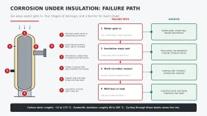
Corrosion under insulation (CUI) is external corrosion caused by water held against the shell. It is hidden, and the first sign is often a leak. As a rough guide, carbon and low-alloy steels are most at risk between about −12 and 175 °C, and austenitic stainless steels, which can suffer chloride stress corrosion cracking, between about 60 and 205 °C. API RP 583 gives detailed guidance.
Ingress Paths and Wet Insulation
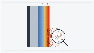
Water reaches the shell by six common paths, shown below: ponding on top heads, open or split jacket seams, failed sealant at penetrations, leaking flanges or process connections, support rings and clips that trap water, and low points with no drain. Once wet, most insulation stays wet, because the jacket that kept water out also keeps it in. Conductivity rises, the shell stays cold and damp, and each shutdown adds another wet–dry cycle.
Coatings, Drainage and Inspection Ports
- Coatings: apply a coating system rated for the operating temperature under the insulation, such as thermal-sprayed aluminium or a suitable high-temperature epoxy, specified to a recognised standard such as AMPP/NACE SP0198.
- Drainage: slope jackets and top heads to shed water, provide drain points at low points, and confirm they cannot become ingress paths themselves.
- Inspection ports: fit removable plugs at condition-monitoring locations, prioritising low points, areas below nozzles, support rings and top heads. Ports allow thickness readings without stripping the insulation.
If CUI has already caused wall loss or a leak, a structured root cause failure analysis will show whether the cause was detailing, material or maintenance.
Analysis and Verification
1D Sizing vs 2D/3D Thermal Models
| Method | Best for | Limits |
| 1D radial calculation | Bulk shell heat loss and surface temperature; sizing thickness | Cannot see nozzles, supports, joints or gaps |
| 2D axisymmetric model | Skirt-to-shell junction, nozzle necks, head-to-shell transitions | Not suited to non-axisymmetric details |
| 3D thermal or thermal-structural model | Nozzle clusters, platforms, closures and local hot spots | More set-up time; needs defensible boundary conditions |
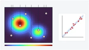
A 1D calculation is the right tool for sizing thickness, but it cannot see thermal bridges, so use 2D or 3D models for the details that carry the risk. Where convection or radiation inside a cavity such as a hot box is hard to estimate, CFD can supply what FEA must assume. Our guides to heat transfer physics and heat transfer in solids cover the underlying modes, and our advanced simulation service applies them.
Surface Temperature, Heat Loss and Transient Checks
- Surface temperature: check hot, still, sunny conditions against the personnel limit, including local hot spots at bridges.
- Heat loss: check cold, windy conditions against the allowable value, and the minimum wall temperature against dew and condensation points.
- Transients: check heat-up time, thermal soak and cool-down, and the temperature gradients that feed thermal stress at supports and nozzles.
Then compare the model with an infrared survey of the finished system to confirm that the as-built details behave as designed.
Installation, Inspection and Lifecycle Management
QA/QC and Weatherproofing
- Complete and inspect surface preparation and coating before any insulation goes on.
- Keep insulation dry in storage and on site, and reject wet material.
- Verify offset joints, sealed laps, flashing and sealant at every penetration, with photographs.
- Record port locations and as-built details, and take a thermographic baseline after the first heat-up.
Removal, Reinstatement and CUI Monitoring
Every time insulation comes off is an inspection opportunity: examine the coating and shell, repair, replace wet insulation, and reinstate to the original detail under QA. Between openings, focus effort where risk is highest. Risk-based inspection (API RP 580 and 581) ranks locations by likelihood and consequence, and targeted ports, periodic thermography and jacket-damage surveys track them. Repair jacket damage quickly, since it is your cheapest CUI barrier. Set a lifecycle plan, including a replacement horizon, before commissioning, not after the first leak.
Frequently Asked Questions
What insulation is used on reactor pressure vessels?
Mineral wool, calcium silicate, cellular glass, perlite and microporous or aerogel products are common, chosen by hot-face temperature, water behaviour, strength and cost, and finished with a metal jacket. Fibrous materials suit most applications if the jacket stays sealed, cellular glass suits wet-prone areas, and microporous products suit thin sections at details.
How is pressure vessel insulation thickness calculated?
Heat flow is calculated radially through the insulation layers using conductivity at mean temperature, together with an outer surface coefficient that reflects wind, emissivity and ambient temperature. Thickness is increased until the surface temperature or heat-loss target is met, following ASTM C680 or ISO 12241. Nozzles, skirts and closures need 2D or 3D models.
How can corrosion under insulation be prevented?
It cannot be eliminated, but it can be controlled: keep water out with a sealed jacket, sloped tops and flashed penetrations; coat the shell under the insulation; provide drainage; use low-chloride materials on stainless steel; and inspect through ports and at planned removals.
When should removable insulation be used?
At items that need regular access, such as flanges, manways, valves, instrument connections and inspection locations. You accept extra heat loss and reinstatement effort in return for access, so control the quality of every refit.
Getting Independent Input on Your Insulation System
Insulation problems tend to surface late, as a hot spot, an energy bill or a leak. A thermal assessment during design, or a review of an existing system, costs far less. Avesta Consulting applies advanced simulation to model heat loss, surface temperature and thermal bridges at nozzles, skirts and closures, and to check the resulting thermal stress. Our design verification service can review an insulation design against its intended functions. If you are designing a new system or assessing an existing one, contact us to discuss it.