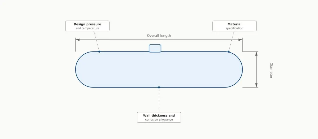
Every pressure vessel that enters service starts as a set of numbers on a page: a design pressure, a temperature range, a material, a wall thickness. Getting those numbers right — and knowing exactly how they were arrived at — is what pressure vessel design actually is. Get them wrong, and the consequences range from an expensive rebuild to a genuine safety incident.
This guide lays out what pressure vessel design covers, why it matters, the stages a design actually goes through, the standards that govern it, and the engineering challenges that come up along the way — with pointers to where we go deeper on each piece across our other guides.
What Is a Pressure Vessel?
A pressure vessel is a sealed container designed to hold a gas or liquid at a pressure substantially different from atmospheric. That pressure differential — not the vessel’s size or contents — is what brings it under design codes such as ASME Section VIII in the first place.
Common Types of Pressure Vessels
| Type | Typical shape | Common use |
| Storage vessels | Horizontal or vertical cylindrical | Holding liquids or gases at pressure with minimal internal process |
| Heat exchangers | Horizontal cylindrical, shell-and-tube | Transferring thermal energy between two fluids |
| Reactors | Vertical cylindrical | Containing and controlling a chemical reaction under pressure |
| Spherical storage | Spherical | Large-volume, high-pressure gas storage such as LPG |
Typical Industrial Applications
- Oil & gas — separators, gas storage spheres, offshore processing equipment
- Chemical and petrochemical processing — reactors, distillation towers, storage vessels
- Power generation — boilers and steam-generating equipment
- Mining and minerals processing — process vessels and pressurized equipment
What Is Pressure Vessel Design?
Pressure vessel design is the engineering process of determining a vessel’s geometry, material, wall thickness, and construction details so that it safely contains its operating pressure and temperature for its intended service life, while meeting the requirements of an applicable design code. It sits between defining what a vessel needs to do and confirming, through calculation and analysis, that the proposed design will actually do it — which is a distinct step covered further below.
Why Pressure Vessel Design Matters
Pressure vessel design isn’t just a compliance exercise — it’s the decision point that determines whether a vessel is safe, cost-effective, and fit for its intended service life.
Safety Considerations
A pressure vessel failure can release stored energy suddenly and violently — the entire discipline of pressure vessel design exists to prevent that outcome. Proper design addresses overpressure, material degradation, and stress concentrations before a vessel is ever fabricated, rather than relying on inspection to catch problems after the fact.
Regulatory Compliance
Pressure equipment is regulated in virtually every jurisdiction, and for good reason — the consequence of failure is high enough that self-certification isn’t considered sufficient. Designing to a recognized code from the outset avoids costly redesign later and is generally a prerequisite for insurance, registration, and operation.
Operational Reliability
A well-designed vessel performs predictably across its service life rather than developing problems at inconvenient or unpredictable intervals. Reliability isn’t a by-product of good design — it’s one of the things good design is explicitly optimizing for, alongside safety and cost.
The Pressure Vessel Design Process
Pressure vessel design moves through a consistent sequence of stages, regardless of the vessel’s size or complexity.
- Defining design requirements
- Material selection
- Structural calculations
- Engineering analysis and simulation
- Design verification
Defining Design Requirements
Every design starts with the operating envelope: design pressure, design temperature, the process fluid and its properties, and the intended service life. These requirements set the boundaries every later decision has to work within — get them wrong or incomplete at this stage, and the error propagates through the entire design.
Material Selection
Material choice balances mechanical strength, corrosion resistance, weldability, and cost against the defined operating conditions. Carbon steel covers the majority of general-service vessels; corrosive or hygiene-sensitive service typically calls for stainless steel, and extreme temperature or chemical exposure can justify a specialty alloy despite the added cost.
Structural Calculations
With requirements and material set, engineers determine the vessel’s basic geometry and wall thickness using the governing design code’s formulas. This establishes a baseline design that satisfies the code’s minimum requirements before more detailed analysis is applied to specific features.
Engineering Analysis and Simulation
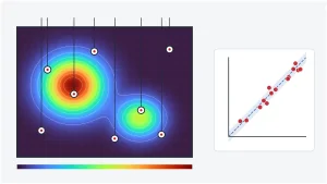
Code formulas are built around idealized geometry — a plain cylindrical shell, for instance — and don’t capture the local stress at nozzles, support attachments, or shape transitions accurately. This is where Finite Element Analysis earns its place in the process, resolving the actual stress distribution at the locations most likely to govern the design. For a broader look at how these simulation methods compare, see FEA vs CFD.
Design Verification
Design verification is the step that closes the loop — an independent check confirming that the finished design, as calculated and analyzed, genuinely meets its stated requirements and code obligations before fabrication begins. This typically means an independent reviewer re-checking the governing calculations, confirming the FEA model’s assumptions and boundary conditions are representative of actual service conditions, and verifying that material certificates and weld procedures align with what the design assumed. It matters because internal sign-off inside the same team that produced the design carries an inherent blind spot; an independent set of eyes catches the errors a design team is structurally less likely to catch in its own work. We cover the practical FEA and hydrostatic testing side of this process in detail in Pressure Vessel Design Verification, and our Design Verification service covers how we support this independently for clients.
Key Design Parameters
| Parameter | Why it matters |
| Internal pressure | The primary driver of shell and head stress, and therefore of required wall thickness |
| Temperature | Affects allowable material stress, thermal expansion, and potential thermal stress |
| Material properties | Governs allowable stress, corrosion resistance, and suitability for the process fluid |
| Corrosion allowance | Extra wall thickness added to account for expected material loss over the vessel’s service life |
Internal Pressure
Design pressure — not simply the normal operating pressure — is what a vessel is actually designed against, and it needs to account for realistic upset conditions, not just steady-state operation. Underestimating this figure is one of the more consequential mistakes a design can make, since it understates the stress the vessel needs to be sized for.
Temperature
Design temperature affects a material’s allowable stress — most materials weaken as temperature rises — and drives thermal expansion, which can introduce mechanical stress of its own where expansion is restrained. Vessels operating across a wide temperature range or subject to thermal cycling need this accounted for explicitly, not assumed away.
Material Properties
Beyond strength, a material’s suitability depends on how it behaves in the actual process environment — its corrosion resistance to the specific fluid involved, its weldability, and its toughness at the vessel’s minimum design temperature. A material that performs well in one service can be entirely wrong for another.
Corrosion Allowance
Corrosion allowance is extra wall thickness added specifically to be consumed by expected corrosion over the vessel’s design life, so that the vessel still meets its structural requirements even after that material loss has occurred. Getting this allowance right depends on realistic assumptions about the process fluid and expected corrosion rate, not a generic default value.
Pressure Vessel Design Standards
Pressure vessel design doesn’t happen in a vacuum — it happens within the framework of a recognized design code, which sets out the calculation methods, material requirements, and safety factors a design has to satisfy.
ASME Section VIII
ASME Section VIII of the Boiler and Pressure Vessel Code is the most widely used pressure vessel design standard globally, and covers everything from basic Division 1 design through to the more analysis-intensive Division 2 and Division 3 approaches for higher-pressure or higher-value equipment. We cover how to choose between these divisions in detail in ASME Section VIII Explained.
Australian Standards
In Australia, pressure equipment is also commonly designed to AS/NZS standards, which align closely with international practice while addressing local registration and in-service inspection requirements. Projects in the Australian market often need to demonstrate compliance with both an international code such as ASME and the relevant local regulatory framework.
Other International Standards
Outside North America and Australia, the European Pressure Equipment Directive (PED) and various ISO standards govern pressure equipment design, testing, and conformity assessment. Multinational projects frequently need to reconcile requirements across more than one of these frameworks.
Common Challenges in Pressure Vessel Design
A handful of engineering challenges show up repeatedly, regardless of the specific vessel or industry.
Fatigue Loading
Vessels in cyclic service — frequent start-stop operation, pressure cycling, or thermal cycling — face a fatigue risk that a static design check doesn’t capture. We cover fatigue mechanisms and analysis methods in more depth in High Cycle vs Low Cycle Fatigue.
Thermal Effects
Temperature gradients and restrained thermal expansion generate mechanical stress on top of pressure loading, particularly in equipment with significant temperature differences across the shell, such as heat exchangers. This is often assessed through thermomechanical analysis, which we introduce as part of our broader structural analysis guide.
Stress Concentrations
Nozzles, support attachments, and shape transitions all create local stress concentrations that idealized code formulas don’t fully capture — which is precisely why FEA has become a standard part of the design process for anything beyond the simplest geometry, rather than an optional extra reserved for unusual cases.
How Engineering Simulation Improves Pressure Vessel Design
Simulation doesn’t replace code-based design — it extends it into the geometry and loading conditions the code formulas were never meant to cover directly. Our Advanced Simulation service applies this across the design process, and our guide to simulation-driven design covers how simulation is increasingly used earlier in the design cycle rather than only as a final check.
| Design challenge | How simulation helps |
| Local stress at nozzles and transitions | FEA resolves actual stress distribution beyond simplified code formulas |
| Combined pressure and thermal loading | Thermal-structural simulation captures interacting effects together |
| Cyclic or fatigue-prone service | Fatigue analysis predicts crack-prone locations before fabrication |
| Complex or non-standard geometry | FEA handles irregular shapes that analytical methods can’t represent |
Alt text: Diagram showing the five stages of the pressure vessel design process in sequence — defining design requirements, material selection, structural calculations, engineering analysis and simulation, and design verification.

Pressure Vessel Design vs Design Verification
These two stages are often mentioned in the same breath, but they answer different questions and are best carried out by different perspectives.
| Aspect | Pressure Vessel Design | Design Verification |
| Purpose | Determines the vessel’s geometry, material, and thickness | Confirms the finished design actually meets its requirements |
| Performed by | The design engineer or design team | Ideally an independent reviewer or third party |
| Question answered | “What should this vessel be?” | “Does this design actually work as intended?” |
| Typical output | Calculations, drawings, and specifications | Verification report confirming compliance and adequacy |
| When it happens | Throughout the design process | Before fabrication, once the design is substantially complete |
Frequently Asked Questions
What is pressure vessel design?
Pressure vessel design is the engineering process of determining a vessel’s geometry, material, and wall thickness so it can safely contain its operating pressure and temperature for its intended service life, in accordance with an applicable design code.
What standards are used for pressure vessel design?
ASME Section VIII is the most widely used standard globally, alongside AS/NZS standards in Australia, the European Pressure Equipment Directive (PED), and various ISO standards, depending on the project’s location and market.
Why is ASME Section VIII important?
ASME Section VIII sets out the calculation methods, material requirements, and safety factors that most pressure vessels are designed against, and offers different design approaches (Divisions 1, 2, and 3) suited to different pressure ranges and levels of analysis effort.
What factors affect pressure vessel design?
The primary factors are internal pressure, temperature, material properties, and corrosion allowance, along with the vessel’s geometry, support arrangement, and any cyclic or thermal loading it will experience in service.
Is FEA used in pressure vessel design?
Yes. FEA is widely used to assess local stress at nozzles, support attachments, and geometric transitions that simplified code formulas don’t capture accurately, and is a standard part of Division 2 and Division 3 design under ASME Section VIII.
What is the difference between pressure vessel design and design verification?
Pressure vessel design determines what the vessel should be — its geometry, material, and thickness. Design verification is an independent check, ideally performed separately from the design team, confirming that the finished design actually meets its stated requirements before fabrication.
Conclusion
Pressure vessel design is less a single calculation than a sequence of decisions — requirements, material, sizing, analysis, and verification — each of which narrows the range of what the finished vessel can safely be. Skipping or rushing any one of those stages doesn’t just risk a code violation; it risks a vessel that looks compliant on paper but isn’t genuinely fit for the service it’s going into.
Need support with pressure vessel design, verification or advanced engineering analysis? Our engineering team helps clients develop safe, compliant and cost-effective pressure vessel solutions. Get in touch to discuss your project.