A water storage tank looks like a simple structure — a cylinder holding a fluid at atmospheric pressure — and that simplicity is exactly why it’s easy to under-scope. There’s no code stamp forcing a rigorous design-by-rule process the way there is for a pressure vessel, yet a tank that fails, leaks, or settles unevenly can take a council’s water supply offline, contaminate a potable system, or collapse under seismic sloshing loads that a static hand calculation never considered.
This guide works through water storage tank design as one connected problem rather than a checklist: how the intended duty sets the capacity and material choice, how hydrostatic, environmental and seismic loads combine at the shell and foundation, and what durability and verification steps actually protect a decades-long asset. It stays focused on atmospheric water storage — potable, fire, process and emergency supply — and doesn’t stray into pressure vessel or oil and gas tank design, which follow a different code framework entirely.
Define the Water Storage Duty
Capacity, Operating Levels and Water Quality
Every tank design decision traces back to duty: how much water needs to be stored, at what operating range, and for whom. Capacity isn’t a single number — it’s a working volume between minimum and maximum operating levels, plus a freeboard allowance above the maximum level to accommodate wave action and seismic sloshing without overtopping. Water quality requirements shape material and lining choices from day one: a potable supply tank has very different internal coating, venting and access requirements than a raw water or process tank, even at the same capacity.
Fire, Potable, Process and Emergency Service
The intended service dictates more than water chemistry. Fire service tanks are typically sized against a required fire flow and duration rather than daily demand, and often need a dedicated fire draw-off point set above a sediment allowance at the tank floor. Potable tanks need water quality safeguards — screened vents, insect-proof overflow, and a roof and access hatch designed to keep the stored volume protected from contamination. Emergency and process tanks sit somewhere in between, but in every case the service class should be fixed before the tank form and structural system are selected, not treated as an afterthought once the shell is sized.
Choose the Tank Form and Material
Ground-Supported vs Elevated Tanks
Ground-supported tanks are the default where site levels already provide adequate supply pressure or where a pump station handles distribution; they’re simpler to construct, inspect and maintain than an elevated tank, and the foundation load path is comparatively straightforward. Elevated tanks — supported on a tower, pedestal or braced steel frame — are chosen where gravity-fed pressure is needed across a distribution network, but they introduce a second structural problem on top of the tank itself: the supporting tower has its own wind, seismic and stability design, and the water’s sloshing dynamics interact with the tower’s own natural frequency in ways a ground tank never has to consider.
Steel vs Reinforced/Prestressed Concrete
Welded or bolted steel tanks dominate for mid-size ground-supported storage: fast to erect, straightforward to inspect, and well suited to standardized shell-course design. Reinforced or prestressed concrete tanks suit larger capacities and sites where long-term durability against a corrosive groundwater or soil environment favours concrete over coated steel — but they bring their own governing failure modes, principally shell cracking and joint leakage rather than corrosion. Prestressing the concrete shell keeps it in compression under hydrostatic load, which is the standard way of controlling through-wall cracking in larger circular concrete reservoirs. The choice between the two is rarely just a cost comparison; it depends on site access for construction, expected service life, and how the tank will be inspected once it’s full of water.
Establish Design Loads
Hydrostatic, Dead, Live and Thermal Loads
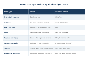
Hydrostatic pressure — increasing linearly with depth — governs shell thickness and, for concrete tanks, reinforcement or prestress at every level of the wall. Dead load includes the structure’s self-weight and any fixed fittings; live load covers roof access, maintenance equipment and, for flat or low-slope roofs, the possibility of rainwater ponding. Thermal effects are often underestimated on tanks: a steel shell exposed to direct sun on one side and shaded on the other develops a temperature differential that generates bending stress at welds and roof-to-shell junctions, particularly on larger-diameter tanks.
Wind, Seismic, Snow and Settlement
Wind load acts on the empty or partially full tank as external pressure on the shell and uplift on the roof — the empty-tank case is often more critical for shell buckling than the full-tank case, because an empty shell has none of the internal hydrostatic pressure that helps stabilise it against external suction. Seismic design for a liquid-filled tank has two distinct components: an impulsive response, where the tank and water move together as a rigid mass, and a convective response, where the free water surface sloshes at its own natural period — a phenomenon that governs freeboard and can drive roof and upper-shell design in high-seismic regions independently of the impulsive base shear. Snow load adds to roof design in cold climates, and differential settlement — where the foundation responds unevenly to the tank’s weight — can distort the shell-to-floor joint even when every individual load case was checked correctly in isolation.
Structural Design by Tank Component
Walls/Shell, Roof and Floor
Shell design for a cylindrical tank is governed by hoop stress from hydrostatic pressure, which is why steel tank shells are typically built in courses of decreasing thickness from bottom to top — the classic variable-thickness-by-height approach. Roofs range from self-supporting cones and domes to rafter-supported flat or shallow-pitch structures, selected based on span, snow load and whether the roof needs to carry equipment. The floor is often treated as the least glamorous but most failure-prone component: it has to accommodate differential settlement, provide adequate slope to a low point for complete drainage, and maintain a reliable seal at the shell-to-floor joint, which is one of the most common leak locations found during in-service inspection.
Columns, Ring Beams, Anchors and Foundations
Elevated and large-diameter roof structures may need internal columns, which introduce their own foundation and buckling checks independent of the shell. A ring beam at the top of the shell stiffens against wind buckling and roof reactions, while a ring beam or footing at the base distributes the shell’s vertical and overturning loads into the supporting soil. Anchor bolts become necessary wherever the tank is light enough, or the seismic overturning moment high enough, that uplift is possible — an under-anchored tank in a seismic zone can lift and rock at the base even though it would never fail under vertical load alone. Foundation design ultimately has to close the loop with a geotechnical assessment of bearing capacity and expected settlement, not just the structural loads generated by the tank.
Hydraulic and Operational Details
Inlets, Outlets, Overflow and Drainage
Inlet and outlet nozzle placement affects both structural local stress at the shell penetration and hydraulic performance — an inlet positioned to create short-circuiting flow straight to the outlet undermines water quality even if the structural design is perfect. Overflow provisions need to handle the maximum credible inflow without surcharging the roof or shell, and a drain at the low point of the floor is what actually makes the tank maintainable, since a tank that can’t be fully emptied can’t be properly inspected or cleaned.
Venting, Access, Mixing and Water Quality
Adequate venting prevents vacuum collapse during rapid drawdown and pressure buildup during rapid filling — both are credible failure modes for a thin-walled atmospheric tank, and vent sizing should be checked against the tank’s actual fill and draw rates, not just a rule-of-thumb nozzle size. Roof access hatches, internal ladders and confined-space provisions matter for ongoing maintenance, and for potable tanks, stagnant zones and short-circuiting between inlet and outlet are a genuine water-quality risk that inlet/outlet geometry and, where needed, mixing systems are designed to address.
Durability, Leakage and Corrosion Control
Crack Control, Joints and Liners
For concrete tanks, crack control comes down to reinforcement detailing, prestress level, and joint design at construction and movement joints — a crack that’s cosmetically minor can still be a leak path once the tank is filled. Liners, whether flexible membrane systems or applied coatings, are used where the base material can’t reliably meet water-tightness or water-quality requirements on its own, and liner selection needs to account for both the stored water chemistry and the mechanical strain the liner will see as the tank fills and empties.
Coatings, Cathodic Protection and Inspection
Steel tanks depend on internal and external coating systems for corrosion control, and internal coatings for potable water need certification for contact with drinking water, not just generic corrosion performance. Cathodic protection is common on tank floors in contact with soil or on the internal floor plate of large tanks, supplementing the coating rather than replacing it. Periodic inspection — visual, ultrasonic thickness surveys, and coating condition assessment — is what actually catches corrosion and cracking before they become a leak or a structural issue, and a structured root cause investigation is the fastest way to work out whether an observed defect is isolated or symptomatic of a wider design or construction issue.
Verification, Construction and Commissioning
Analysis Models and Code Checks
Standard shell, roof and foundation checks cover most tank geometries using established design-by-formula methods, similar in spirit to the approach we describe in What Is Structural Analysis?. Where a tank has an unusual aspect ratio, heavy roof-mounted equipment, or sits in a high-seismic zone, finite element analysis is used to check shell buckling and seismic sloshing behaviour more precisely — the same linear vs nonlinear distinction that applies to buckling checks on pressure vessels applies here, since an elastic eigenvalue buckling check on an empty steel shell under wind suction can be non-conservative compared with a large-deflection nonlinear analysis. Tank design software and general structural analysis tools both have a role, and for elevated tanks or tanks in exposed coastal or offshore-adjacent sites, the environmental load methods used for marine and coastal structures are directly applicable to wind and seismic assessment of the supporting structure.
Testing, Disinfection and Handover Records
Before handover, a water storage tank needs a hydrostatic or water test to confirm shell and floor integrity under real load — not just calculated capacity, but observed leak-tightness under an actual fill. Potable tanks require disinfection and water quality testing before they’re connected to a live supply, following standard chlorination and flushing procedures. Handover records — as-built drawings, material certificates, weld and coating inspection reports, and the test and disinfection results — become the baseline against which every future inspection is compared, and a tank commissioned without that baseline is much harder to assess accurately later in its service life.
FAQ
What loads are considered in water tank design?
Water tank design accounts for hydrostatic pressure from the stored water, dead and live loads, wind, seismic loads (both impulsive and sloshing/convective), snow where relevant, thermal effects, and differential foundation settlement.
Which material is best for a water storage tank?
There’s no single best material — steel suits fast construction and standardized mid-size tanks, while reinforced or prestressed concrete suits larger capacities and sites where long-term durability against a corrosive environment favours concrete. The right choice depends on capacity, site access, service life expectations and maintenance strategy.
How are elevated water tanks designed for earthquakes?
Elevated tanks are checked for both impulsive response, where the tank and water move with the supporting structure, and convective sloshing of the free water surface, which has its own natural period. The supporting tower or pedestal also needs its own seismic stability and overturning check, since it carries the combined mass of the tank and its contents.
What tests are required before commissioning a water tank?
A hydrostatic or water test confirms shell and floor integrity under actual fill conditions, and potable water tanks additionally require disinfection and water quality testing before connection to a live supply, with results documented as part of the handover record.
Verifying Your Water Storage Tank Design
A water storage tank’s reliability depends on how well its shell, roof, foundation and hydraulic details work together over decades of service, not just on whether each component passes its own isolated check. If you’re designing a new tank, evaluating a proposed design, or assessing an existing tank showing signs of distress, Avesta Consulting’s design verification and root cause failure analysis teams can review the structural, hydraulic and durability aspects together. Get in touch to discuss your project.