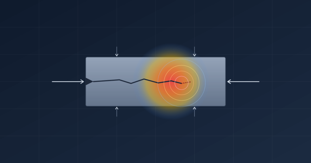
A component doesn’t need to be overloaded to fail. It can be sitting well within its rated stress range, carrying a load it was designed for, and still crack apart — because somewhere in the material there was already a flaw, and that flaw grew every time the load cycled. This is the blind spot that traditional stress analysis leaves open, and it’s the exact gap fracture mechanics was developed to close.
Fracture mechanics is the branch of engineering that studies how cracks initiate, grow, and eventually cause a component to fail — even when the surrounding material never exceeds its allowable stress. For anyone responsible for pressure equipment, pipelines, mine infrastructure, or heavy industrial structures, understanding fracture mechanics isn’t academic. It’s the difference between catching a crack while it’s still manageable and finding out about it after a shutdown, a failure investigation, or worse.
What Is Fracture Mechanics?
At its core, fracture mechanics is an engineering discipline that treats a crack as a real, measurable feature of a component rather than an assumption to be designed away. Instead of asking “is the stress in this part below the material’s yield strength?”, fracture mechanics asks a more specific question: “given that a crack of a certain size already exists, will it grow, how fast, and at what point will it cause the component to fail?”
That shift matters because real components are never flaw-free. Welds contain porosity and inclusions. Castings have shrinkage defects. In-service equipment picks up corrosion pits, machining marks, and fatigue damage over years of operation. Traditional design methods assume a defect-free part and apply a safety factor to cover the unknown. Fracture mechanics instead models the defect directly, using material properties, crack geometry, and applied loading to predict behaviour with far more precision — which is exactly why it sits at the centre of most serious failure investigations and fitness-for-service assessments.
Why Fracture Mechanics Matters in Engineering
- It predicts failure in components that pass conventional stress checks
- It quantifies how much life remains in a cracked or flawed component
- It underpins fitness-for-service decisions on ageing or in-service assets
- It provides the technical basis for inspection intervals and repair-or-replace decisions
- It gives failure investigators a way to confirm — not just guess — how a component actually failed
Preventing Catastrophic Failures
Most catastrophic equipment failures — vessel ruptures, pipeline bursts, structural collapses — don’t happen because someone got the stress calculation wrong. They happen because a crack was present, went undetected or unassessed, and grew to critical size under normal operating loads. Fracture mechanics gives engineers a way to catch that scenario before it happens, by calculating whether a known or suspected flaw is stable under service conditions or whether it’s on a trajectory toward failure.
Extending Equipment Life
Not every crack found during an inspection needs an immediate shutdown and replacement. Fracture mechanics allows engineers to calculate a remaining-life estimate for a flawed component — how many more cycles, or how much more operating time, it can safely tolerate before the crack reaches a critical size. That calculation is often the difference between an unplanned outage and a scheduled repair at the next planned maintenance window.
Supporting Asset Integrity Decisions
Asset owners are regularly faced with a defect found during inspection and a decision to make: run, repair, or replace. Fracture mechanics turns that decision from a judgement call into an evidence-based one, giving engineering, maintenance, and reliability teams a shared, defensible basis for what happens next — which matters as much to insurers and regulators as it does to the plant itself.
The Basics of Fracture Mechanics
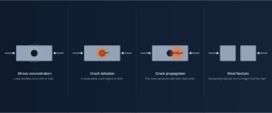
Every fracture, regardless of the material or the application, tends to follow a similar sequence. Understanding that sequence is the foundation for everything else in fracture mechanics.
Stress Concentrations
Cracks don’t start in the middle of a uniformly loaded, smooth section of material. They start where stress is locally amplified — at a notch, a weld toe, a sharp corner, a hole, or a surface defect. These stress concentrations raise the local stress well above the nominal stress in the surrounding material, even when the overall component is loaded conservatively. It’s this local amplification, not the average stress in the part, that determines where and when a crack begins.
Crack Initiation
At a stress concentration, repeated loading — or, less commonly, a single severe overload — causes microscopic damage to accumulate until a detectable crack forms. In welded and fabricated equipment, this stage is often shortened or skipped entirely, because a fabrication flaw effectively starts life as a crack already. This is one of the reasons weld quality and inspection standards carry so much weight in pressure equipment and structural fabrication.
Crack Propagation
Once a crack exists, it doesn’t grow at a constant, easily guessed rate. Under cyclic loading, a crack typically advances a small, measurable amount with every load cycle, and that growth rate depends on the crack’s current size, the material’s resistance to cracking, and the loading conditions it experiences. Fracture mechanics is largely concerned with modelling this stage, because it’s where engineers have the best opportunity to intervene — through inspection, monitoring, or a planned repair — before the crack becomes unmanageable.
Final Fracture
Eventually, a growing crack reaches a size at which the remaining material can no longer carry the applied load, and the component fails — sometimes gradually, often suddenly. The point at which this happens is governed by the material’s fracture toughness and the crack’s size and orientation. Predicting this critical point, well ahead of time, is the entire purpose of fracture mechanics as an engineering tool.
Types of Fracture
Not every fracture happens the same way, and the type of fracture tells an investigator a great deal about what actually caused it.
| Fracture Type | Typical Behaviour | Warning Signs |
| Brittle Fracture | Sudden, little to no plastic deformation | Often none before failure |
| Ductile Fracture | Gradual, with visible deformation before failure | Bulging, necking, visible distortion |
| Fatigue Fracture | Progressive crack growth under cyclic loading | Beach marks, striations on fracture surface |
Brittle Fracture
Brittle fracture happens quickly and with almost no warning — the material separates with little or no plastic deformation beforehand. It’s most commonly associated with low-temperature service, certain high-strength steels, and materials operating below their ductile-to-brittle transition temperature. A classic industrial example is a steel structure or pressure vessel that fractures during a cold-weather startup, when the material’s toughness has dropped below the level needed to resist the flaw sizes present.
Ductile Fracture
Ductile fracture is the more forgiving failure mode. The material deforms visibly — stretching, thinning, or bulging — before it finally separates, which often gives operators and inspectors a window to notice something is wrong before complete failure occurs. Overloaded piping and vessels that fail during an upset condition, rather than in normal service, often show this kind of visible distortion at the failure location.
Fatigue Fracture
Fatigue fracture is the result of repeated loading and unloading, even when every individual load cycle stays well within the material’s allowable stress. It’s the most common failure mechanism in rotating equipment, cyclically loaded structures, and any component subject to vibration or repeated pressure and thermal cycling. Because fatigue cracks can grow for a long time before they become visible or cause a noticeable problem, fatigue failures are frequently the ones that catch operators by surprise. A closer look at how cyclic loading drives this process is covered in our dedicated fatigue analysis work.
Key Concepts in Fracture Mechanics
A handful of core concepts underpin almost every fracture mechanics assessment. None of them require getting into the underlying mathematics to understand what they mean in practice.
Stress Intensity Factor (K)
The stress intensity factor describes how much a crack amplifies the stress field around its tip, accounting for the crack’s size, shape, and the way the component is loaded. Two cracks of different sizes in the same component, under the same load, will have different stress intensity factors — and it’s this value, rather than the nominal stress in the part, that determines whether a given crack is likely to grow.
Fracture Toughness
Fracture toughness is a material property that describes how resistant a material is to crack propagation before it fractures. A tough material can tolerate a relatively large crack without failing; a brittle material may fail with only a small, sometimes undetectable flaw present. Fracture toughness varies with temperature, material condition, and manufacturing process, which is why material selection and heat treatment specifications matter so much for equipment operating in demanding environments.
Crack Growth Rate
Crack growth rate describes how quickly a crack advances with each cycle of loading. This value is central to any remaining-life calculation, because it allows an engineer to project forward from a measured or assumed crack size today to the point at which that crack would reach a critical size — the basis for setting a safe inspection interval or a run/repair/replace decision.
Linear Elastic Fracture Mechanics (LEFM)
Linear Elastic Fracture Mechanics, or LEFM, is the most widely applied fracture mechanics framework in industrial engineering. It assumes the material surrounding a crack behaves elastically — meaning any deformation is small and largely recoverable — which holds true for a large share of practical cases involving high-strength metals and moderate loading. LEFM is the model behind most crack growth and remaining-life assessments carried out on pressure equipment, pipelines, and structural steelwork, precisely because it strikes a workable balance between accuracy and the amount of material and loading data needed to run the assessment. Where a component experiences significant plastic deformation around the crack tip, more advanced elastic-plastic fracture mechanics methods are used instead — but for the majority of industrial assessments, LEFM is the starting point.
Fracture Mechanics Applications
| Application | Why Fracture Mechanics Is Used |
| Pressure Vessels | Assess flaws found during inspection against safe operating limits |
| Pipelines | Evaluate corrosion, weld defects, and third-party damage |
| Mining Equipment | Manage fatigue cracking in heavily cyclic, high-load equipment |
| Heavy Industrial Structures | Assess structural steelwork for crack growth under cyclic or dynamic loads |
Pressure Vessels
Pressure vessels are one of the most common places fracture mechanics gets applied in practice, because the consequences of a missed flaw are severe and the regulatory expectations are correspondingly high. When an inspection turns up a crack-like indication in a vessel shell, nozzle, or weld, fracture mechanics is used to determine whether that flaw is acceptable for continued service, and if so, for how long — work that sits alongside the broader verification process covered in Pressure Vessel Design Verification.
Pipelines
Pipelines accumulate flaws over decades of service — corrosion, mechanical damage from third-party contact, weld defects from original construction — and fracture mechanics is the standard tool for deciding whether a detected flaw needs immediate repair or can be safely monitored. Given the length of most pipeline networks, this kind of assessment is often what makes a risk-based inspection program economically viable, rather than repairing every flaw the moment it’s found.
Mining Equipment
Mining and mineral processing equipment operates under some of the harshest cyclic loading conditions in industry — repeated impact, vibration, and high-tonnage handling that drives fatigue cracking in structural supports, chutes, and rotating components. Fracture mechanics is regularly used here to understand how quickly a detected crack is likely to grow under that loading, informing whether a piece of equipment can run until the next scheduled shutdown or needs earlier intervention.
Heavy Industrial Structures
Structural steelwork subject to dynamic or cyclic loads — crane runways, support structures for reciprocating equipment, and steelwork in high-vibration environments — can develop fatigue cracks at welds and connection details over time. Fracture mechanics assessment of these cracks complements broader structural analysis work by addressing the specific question of how an existing flaw will behave, rather than how the structure performs when assumed flaw-free.
Fracture Mechanics vs Traditional Stress Analysis
| Factor | Traditional Stress Analysis | Fracture Mechanics |
| Core assumption | Material is free of significant flaws | A crack or flaw is present and is explicitly modelled |
| Key question | Is stress below the material’s allowable limit? | Will an existing crack grow, and when will it become critical? |
| Failure criterion | Yield or ultimate strength exceeded | Stress intensity exceeds fracture toughness |
| Best suited to | New designs with no known defects | In-service equipment, inspection findings, fitness-for-service |
| Typical output | Safety factor against yielding or buckling | Critical crack size, remaining life, safe inspection interval |
Traditional stress analysis and fracture mechanics aren’t competing approaches — they answer different questions, and most robust engineering programs use both. Stress analysis confirms a new design has adequate margin under expected loads, assuming sound material and fabrication. Fracture mechanics takes over once a flaw is known or suspected to exist — whether that’s a defect found during fabrication inspection, damage discovered in service, or a crack identified during a shutdown — and answers the question stress analysis was never built to answer: given this crack, how much longer can this component safely operate?
How Fracture Mechanics Supports Failure Analysis
When a component fails and the cause isn’t obvious, fracture mechanics is often what turns a plausible theory into a confirmed finding. A fracture surface carries a physical record of how the crack grew — features like beach marks and striations point to fatigue, while the absence of visible deformation points toward brittle fracture, and each of these observations can be checked against a fracture mechanics calculation to see whether the loading history the equipment actually experienced is consistent with the crack growth found on the part.
This is what separates a defensible failure finding from an educated guess. It’s not enough to say a component “failed from fatigue” — a proper investigation calculates whether the stress intensity at the crack tip, given the component’s actual loading history and the flaw size present, was consistent with the crack growth observed on the fracture surface. That calculation either supports the fatigue hypothesis or rules it out in favour of overload, brittle fracture, or a material defect — and it’s this kind of evidence-based confirmation that regulators, insurers, and engineering sign-off processes increasingly expect. It’s also why fracture mechanics sits alongside fatigue analysis and finite element modelling as one of the core engineering tools used in Root Cause Failure Analysis investigations — RCFA identifies that a physical failure occurred and needs technical confirmation; fracture mechanics is frequently the discipline that provides it.
Once a failure mechanism is confirmed, fracture mechanics also feeds directly into what happens next — informing design changes, material substitutions, or revised inspection intervals that get checked against the original requirements through design verification before they’re implemented.
Common Engineering Mistakes Related to Cracking
- Assuming a component that passes a standard stress check has no flaws worth assessing, rather than confirming through inspection
- Treating every crack finding the same way, without assessing its specific size, location, and growth potential
- Ignoring the effect of operating temperature on fracture toughness, particularly for equipment exposed to cold startups
- Using a generic remaining-life estimate instead of one based on the component’s actual loading history and material properties
- Delaying a fracture mechanics assessment until after a failure, rather than using it proactively on inspection findings
- Assuming a repaired or ground-out flaw carries no further risk without reassessing the repaired area under service loading
Frequently Asked Questions
What is fracture mechanics in engineering?
Fracture mechanics is the engineering discipline that studies how cracks initiate, grow, and cause components to fail, using material properties, crack geometry, and loading conditions to predict whether an existing flaw is safe to leave in service and for how long.
What is the difference between fracture mechanics and stress analysis?
Traditional stress analysis assumes a component is free of significant flaws and checks whether stress stays below an allowable limit. Fracture mechanics assumes a crack already exists and calculates whether it will grow and when it might reach a critical, failure-causing size.
What causes crack propagation?
Crack propagation is most commonly driven by repeated cyclic loading, where a crack advances a small amount with each load cycle. Environmental factors such as corrosion, high temperature, and aggressive chemical exposure can also accelerate crack growth.
What is fracture toughness?
Fracture toughness is a material property describing how resistant a material is to crack propagation before it fails. Tougher materials can tolerate larger flaws without failing, while more brittle materials may fail with only a small, sometimes undetectable crack present.
What is LEFM?
LEFM, or Linear Elastic Fracture Mechanics, is a fracture mechanics framework that assumes the material around a crack behaves elastically. It’s the most widely used approach for assessing cracks in high-strength metals and moderately loaded industrial equipment.
When should fracture mechanics be used?
Fracture mechanics should be used whenever a crack or crack-like flaw is found or suspected — during fabrication inspection, in-service inspection, or a failure investigation — and a decision needs to be made about whether the component is safe to continue operating.
Conclusion
Fracture mechanics fills a gap that traditional stress analysis was never designed to close: what happens once a flaw is already there. For engineers and asset owners managing pressure vessels, pipelines, mining equipment, and heavy industrial structures, that gap is exactly where the most serious and most preventable failures tend to occur. Understanding whether a detected crack is stable, how quickly it’s likely to grow, and when it becomes a genuine risk turns an uncertain inspection finding into a defensible engineering decision.
Need support assessing crack growth, structural integrity or failure mechanisms? Our engineering team provides fracture mechanics assessments, failure investigations and advanced engineering analysis services. Get in touch to talk through your equipment.