Most discussions of reactor vessel design stop at the shell: wall thickness, head geometry, nozzle reinforcement, material selection. We’ve covered that ground in Reactor Pressure Vessel Design and in Design of Pressure Vessels: A Complete Guide. What tends to get less attention is the support system underneath the vessel — the skirt, saddle, lugs or ring that carry the vessel’s weight, resist lateral and seismic loads, and transfer every one of those forces into the foundation.
That’s a mistake, because the support is rarely a single-discipline problem. It sits at the intersection of pressure vessel mechanics, structural steel design, geotechnical capacity and piping flexibility, and a support that looks adequate in isolation can still fail because of how loads combine at the connection. This article works through that interface: the loads a reactor vessel support must resist, the common configurations, how the vessel-to-support connection is verified, and what a practical inspection and verification program looks like. It does not re-cover shell sizing or code-by-rule wall thickness — see the guides linked above for that.
What the Reactor Vessel Support System Must Do
Vertical, Lateral and Hold-Down Functions
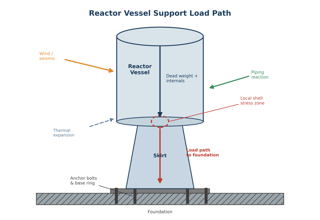
A reactor vessel support has three jobs happening at once. It must carry the vertical dead weight of the vessel, its internals and the process fluid down to the foundation. It must resist lateral loads — wind, seismic, and piping thrust — without allowing excessive sway or rocking. And under uplift conditions, whether from seismic overturning or an empty vessel in high wind, it must hold the vessel down rather than letting it lift off its base. Anchor bolts are usually the last line of defence for that third function, which is why their sizing is rarely a formality.
Alignment, Accessibility and Thermal Accommodation
Beyond strength, the support has to keep the vessel aligned with connected piping and internals over the full range of operating conditions, allow access for inspection of welds and bolting, and accommodate the vessel’s thermal growth without locking in restraint forces. A support that satisfies the strength checks but binds against thermal expansion will eventually show up as cracked grout, elongated bolt holes, or unexplained nozzle loads on the attached piping.
Design Loads and Load Combinations
Dead Weight, Internals and Piping Reactions
The baseline load case is straightforward: empty weight, internals, catalyst or fill weight, and the operating or hydrotest fluid weight, whichever governs. Piping reactions are less straightforward. Attached piping applies forces and moments to the vessel nozzles that are then carried through the shell into the support — and those reactions depend on the pipe stress analysis, not just the vessel itself. Coordinating pipe stress and vessel support design early avoids a common late-stage surprise, where a support sized for vessel weight alone turns out to be under-designed once nozzle loads are added.
Seismic, Thermal Transient and Accident Loads
Seismic loads govern lateral and overturning design in many regions, and for tall, top-heavy reactor vessels the overturning moment at the base can dominate the anchor bolt sizing even when the seismic acceleration itself is modest. Thermal transients — startup, shutdown, and upset conditions — introduce time-dependent stress at the support connection that a single steady-state load case will miss. Where applicable, accidental loads such as blast, impact or a stuck relief valve reaction need their own load combination rather than being folded into the standard operating cases.
Common Support Configurations
Skirts, Support Lugs and Support Rings
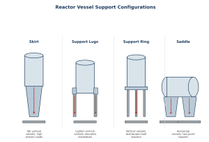
Skirt supports are the default for tall vertical reactor vessels, particularly where seismic loads are significant: the cylindrical or conical skirt distributes the reaction around the full shell circumference and keeps the load path close to axisymmetric. Support lugs are simpler and cheaper for lighter, elevated vessels, but concentrate load at a small number of points, which raises the local shell stress at each lug relative to a skirt. Support rings sit between the two, spreading the reaction around the shell while allowing a lighter structural interface below.
Saddles and Special Reactor Arrangements
Horizontal reactor vessels use saddle supports, typically two per vessel, sized to control both the bending moment in the shell between saddles and the local stresses at the saddle horns. Some reactor arrangements — fluidized bed units, or vessels with heavy internal cyclones — carry enough eccentric or dynamic load that a hybrid arrangement, such as a skirt combined with lateral guides, ends up being the practical solution. The right configuration depends on vessel proportions, internals, and site seismicity as much as on cost.
Vessel-to-Support Connection Design
Local Shell Stress and Reinforcement
The skirt-to-shell or lug-to-shell weld is usually the highest-stressed detail in the entire support system, because it’s where a concentrated reaction meets a relatively thin pressure shell. Local stress at this junction is checked against shell discontinuity stress limits, often using the same category of methods used for nozzle reinforcement — WRC 107/537-type local load methods, or shell discontinuity analysis for skirt junctions. Where the calculated stress exceeds allowable limits, a reinforcing pad, a thickened insert plate, or a taper in the skirt profile is used to bring the local stress back within limits without over-thickening the entire shell.
Anchor Bolts, Base Plates and Concrete Interface
Below the skirt or lug, the base ring, anchor bolts and concrete interface carry the accumulated load into the foundation. Anchor bolt design has to account for combined tension and shear under overturning, bolt pre-tension losses over time, and edge distance and embedment requirements in the concrete — a bolt that passes a simple tension check can still fail the concrete breakout or pullout check if it’s placed too close to a foundation edge. Base plate thickness and stiffening are sized to keep bolt loads reasonably uniform and to avoid excessive plate flexure between bolts.
Thermal Effects and Restraint
Differential Expansion and Thermal Gradients
A reactor vessel operating well above ambient temperature grows more than the structure supporting it, and that differential has to go somewhere. Left unaccommodated, it shows up as restraint stress at the support connection, distorted anchor bolts, or piping loads transmitted back through supposedly free nozzles. Thermal gradients through the skirt wall — hot at the shell end, cooler toward the base ring — add a secondary bending stress that is easy to overlook if the support is only checked under uniform-temperature assumptions.
Hot-Box Details and Sliding/Guided Supports
Two details manage this in practice. A hot-box or insulated skirt reduces the thermal gradient across the skirt wall by keeping the skirt closer to shell temperature, which lowers the secondary bending stress at the base. For saddle-supported horizontal vessels, one saddle is typically fixed and the other allowed to slide, using PTFE slide plates or similar low-friction interfaces, so the vessel can grow axially without dragging both saddles and their anchor bolts along with it.
Analysis and Verification
Code Equations and Local Stress Methods
For many skirt, saddle and lug configurations, published code equations and design-by-formula methods give a fast, defensible first pass — the kind of approach covered under ASME Section VIII and, for Australian projects, AS 1210. These methods are efficient for standard geometries and load combinations, but they rely on assumptions about load distribution and boundary conditions that don’t always hold for unusual support geometries, closely spaced nozzles near the support, or heavily eccentric internals.
FEA, Buckling and Seismic Qualification
Where the geometry or load combination falls outside the range the hand methods were derived for, finite element analysis fills the gap — our overview of structural analysis methods covers the general toolkit, and the choice between linear and nonlinear treatment (see Linear vs Nonlinear Structural Analysis) matters specifically for skirt buckling checks, where large-deflection, elastic-plastic analysis gives a more realistic buckling capacity than a linear eigenvalue estimate alone. Seismic qualification of the support typically combines a response spectrum or time-history analysis of the vessel-support system with the local stress and buckling checks at the base.
Inspection, Fatigue and Lifecycle Risks
Weld Hotspots and Accessible Inspection Zones
The skirt-to-shell weld, lug attachment welds, and the base ring weld are the recurring hotspots for cracking over a vessel’s life, precisely because they carry the concentrated local stress identified at the design stage. A support design that leaves these welds physically inaccessible for future ultrasonic or magnetic particle inspection creates a maintenance problem that no amount of design margin fully offsets — inspection access should be planned in alongside the stress calculation, not added afterward.
Ageing, Settlement and Modification Checks
Over decades of service, foundations settle, anchor bolts lose pretension, and grout can crack or lose contact with the base plate — any of which changes how load actually reaches the foundation compared with the original design assumption. Cyclic thermal and mechanical loading over many startup-shutdown cycles is a fatigue mechanism at the support connection just as it is elsewhere on the vessel (see our vibration and fatigue analysis work), and any later modification — adding piping, changing internals, or re-rating the vessel — should trigger a re-check of the support loads rather than an assumption that the original design still governs. When a support does show unexpected distress, a structured root cause failure analysis approach is usually faster than ad hoc troubleshooting at identifying whether the cause is a load that changed, a detail that was never quite right, or straightforward ageing.
FAQ
How is a reactor pressure vessel supported?
Most vertical reactor vessels use a skirt support welded to the bottom head or lower shell, transferring load through a base ring and anchor bolts into the foundation. Lighter vertical vessels may use support lugs, and horizontal vessels use two saddle supports.
What loads act on reactor vessel supports?
Supports carry dead weight and internals, wind and seismic lateral loads, piping reactions transmitted through the vessel nozzles, thermal expansion effects, and — where relevant — accidental loads such as blast or impact.
When is a skirt support used for a vertical vessel?
Skirts are typically chosen for tall vessels and for sites with significant seismic demand, because the full-circumference connection distributes the reaction more evenly than a small number of discrete lugs.
How are thermal stresses checked at a vessel support?
Thermal stress at the support is checked by evaluating the differential expansion between the vessel and the supporting structure, the through-wall thermal gradient in the skirt, and, where the support isn’t free to move, the restraint force generated by preventing that growth.
Verifying Your Reactor Vessel Supports
A reactor vessel support is only as reliable as the weakest link in the chain from shell to foundation — and that chain runs through local shell stress, weld detailing, anchor bolts and the concrete interface, often under load combinations that aren’t obvious until they’re checked together. If you’re scoping a new reactor vessel support or reviewing an existing one, Avesta Consulting’s design verification and advanced simulation teams work through exactly this kind of support, anchor and local attachment stress analysis. Get in touch to discuss your project.